Transformer Short-Circuit Withstand Evidence for African EPC Bids: From Fault Study to Factory Release
Zisheng Electric often sees a short-circuit withstand statement reduced to a single line in an EPC bid: “Complies with IEC 60076-5.” That line is a useful starting point, but it does not tell the buyer which transformer design was assessed, what external fault duty the project presents, or whether the offered winding and clamping arrangement is covered by the evidence. For African industrial and infrastructure projects, a transformer short-circuit withstand evidence review should connect the network study, the guaranteed design and the manufacturer’s records before the purchase order is released.
Why transformer short-circuit withstand evidence needs a project boundary
An external short circuit exposes a transformer to thermal heating and electrodynamic forces. The current magnitude and duration depend on the upstream source, transformer impedance, fault location, protection settings and the contribution of connected sources. The mechanical force is particularly sensitive to current peaks. A declaration for one design cannot simply be transferred to a different winding geometry, tap arrangement or support system because the internal force paths may change.
The IEC’s description of IEC 60076-5:2006 addresses the ability of a power transformer to sustain external short-circuit overcurrents without damage. It describes thermal calculation and both special-test and theoretical-evaluation routes for dynamic effects. The standard’s public summary does not, by itself, establish that a particular offered unit has passed a short-circuit test. The EPC team still needs a traceable technical file and an agreed acceptance route.
Start the review with the project’s short-circuit study, not a generic catalogue value. Ask the network designer for the maximum and minimum prospective fault levels at the transformer terminals, the assumed source configuration, future generation or motor contribution, the protective clearing times and any operating configurations that create a stronger source. If those inputs are provisional, mark the guarantee review provisional as well. A tender that hides a missing fault study behind a general compliance claim is not ready for a final release decision.

Freeze the electrical duty used for the bid comparison
The single-line diagram should identify the source side, connection points, tap range, vector group and earthing arrangement. The short-circuit study should state its base values and the operating case that produces the governing duty. A transformer connected to a utility network, on-site generators or a hybrid source may see different cases. It is the project engineer’s responsibility to define those cases; no national grid fault level should be inferred merely from a country name.
Transformer impedance influences fault current, voltage regulation and parallel operation. A lower impedance may ease voltage drop during motor starts, while it can increase downstream fault duty. A higher impedance can reduce a fault current but alter process voltage performance. The EPC comparison therefore needs the guaranteed impedance at stated reference conditions and tap positions, plus the tolerance and any maximum/minimum values the system study uses. The voltage-regulation and motor-starting review is a useful companion to this fault-duty discussion.
Do not assume a protection relay’s nominal setting is the actual fault duration. Review the complete clearing chain: sensing, relay logic, breaker opening, back-up protection and credible breaker failure cases. The project specification should say which duration is used for thermal assessment and which fault cases are excluded by the agreed system boundary. The manufacturer should not be asked to certify an unspecified future network.
Build an evidence matrix before approving the offered design
The table below is a procurement review aid, not a substitute for the applicable standard or a project short-circuit calculation. Each row ties a design input to the evidence the buyer can request and the decision it supports.
| Decision item | Project input to freeze | Supplier evidence to request | Release question |
|---|---|---|---|
| External fault duty | Maximum source configuration, fault locations, peak and symmetrical current assumptions, clearing time | Design duty statement linked to the agreed study revision | Does the assessment cover the governing operating case? |
| Impedance and taps | Guaranteed impedance, reference basis, tolerance and tap range | Guaranteed data sheet and impedance test plan/results | Are the bid and network model using the same values? |
| Thermal withstand | Fault current and protection duration | Calculation summary, assumptions and design reference | Is the time/current case traceable to the study? |
| Dynamic withstand | Peak-duty case and winding configuration | Applicable special-test report or justified theoretical evaluation, with similarity mapping | Does the evidence actually represent the offered construction? |
| Manufacturing control | Approved winding, insulation and clamping drawings | Inspection and change-control records for the offered unit | Could a later design change invalidate the evidence? |
| Factory release | Approved inspection and test plan | Routine test reports, deviations and closure records | Can the buyer connect this serial-numbered unit to the approved file? |
In a multi-vendor tender, ask every bidder to complete the same matrix. A missing test report should not automatically be scored as a failure if the specification permits a theoretical evaluation. Equally, a report for a different transformer rating should not be accepted merely because its headline short-circuit current looks higher. The relevant comparison is design similarity and the agreed method of demonstrating withstand.

Read a short-circuit test report with design identity in mind
A special-test report is valuable when the tested construction can be related to the offered unit. Check the test object identity, rating, voltage combination, winding arrangement, tap position, impedance, short-circuit current and test sequence. Then ask how the offered transformer’s conductor arrangement, radial and axial support, lead routing, clamping and insulation system compare. A different winding height or changed lead exit may matter even if the nameplate ratings appear similar.
Traceability should be explicit. A supplier can provide a comparison table identifying the tested unit, offered unit, differences and engineering rationale for each difference. Ask who approved the similarity assessment and whether the referenced report is complete and legible. Redacted proprietary drawings can still show controlled document numbers, revision status and enough engineering detail for a technical assessment. If confidentiality limits disclosure, agree an inspection route with the owner’s engineer instead of accepting a bare assertion.
For an evaluation route based on analysis, request the assumptions and the boundaries of the model, including how conductor forces and support strength were considered. The public IEC summary recognizes a theoretical-evaluation route for dynamic effects; it does not make every calculation equally persuasive. An unexplained spreadsheet value does not establish the construction’s mechanical behavior. The reviewer should be able to follow the chain from fault case to winding force, support response and documented acceptance.
Do not describe a routine factory test as a short-circuit withstand test. Routine measurements are important for the delivered unit, but they have different purposes. The buyer can use them to verify that the as-built transformer remains consistent with the guaranteed design and to establish a baseline. A special short-circuit test, where specified and performed, is a separate evidence item.
Connect the evidence to the actual transformer build
Even a strong type-test file loses value if the ordered unit changes after approval. Define a hold point for winding and clamping drawings, and identify changes that trigger a fresh engineering review. Examples include conductor dimensions, radial spacers, axial blocking, pressboard parts, lead supports, tap arrangement or a different winding supplier. Not every minor fabrication change affects short-circuit withstand, but the disposition must be documented rather than decided informally on the shop floor.
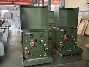
Manufacturing inspection should follow the features relied on in the analysis: winding dimensions, conductor transposition where applicable, insulation clearances, spacer placement, clamping pressure process and lead restraint. An inspector need not claim to calculate forces by sight. The practical question is whether the agreed design features are present and the records identify the correct unit and revision. Photographs are useful supporting evidence when dated and linked to the serial number, but they are not a substitute for controlled measurements.
At FAT, reconcile the nameplate and test schedule with the approved data sheet. Record impedance and winding resistance at the specified reference conditions and tap positions, along with other agreed routine-test results. Compare each result to its contractual acceptance basis. If a measured impedance moves toward a system-study limit, return the result to the system engineer rather than treating a factory pass as automatic project acceptance. The procurement team can consult the mining bid review of harmonic guarantees and short-circuit evidence for another example of joining bid data to system duty.
Separate supplier compliance, owner approval and utility interface
Three approvals are often conflated. The manufacturer confirms what its design and documentation support. The EPC engineer confirms that the specified network duty and equipment interfaces are correctly represented. The owner or utility accepts the arrangement under the project contract. A supplier’s IEC statement cannot replace a site-specific fault study or an owner-approved protection philosophy.
For projects with an external utility connection, obtain the actual connection conditions from that utility or the approved project studies. Do not borrow fault-level values, frequency, voltage or protection requirements from another country or a nearby project. Clarify whether the transformer is on the utility or customer side of the point of connection, who owns the upstream breaker, and which party supplies the final settings. The technical deviation register provides a way to close differences between tender assumptions and the approved connection package without burying them in meeting minutes.
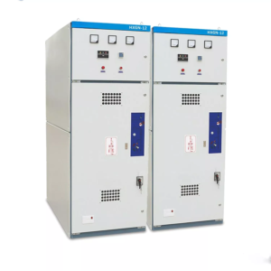
A coordinated review also considers connected equipment. Check that switchgear interrupting and making ratings, cables, bus ducts, CTs, protective relays and earthing arrangements are compatible with the studied fault duty. A transformer can be adequately designed while the installation remains incomplete as a system. Where surge protection or insulation coordination is also in scope, the surge arrester coordination guide addresses a different but adjacent interface.
Handle uncertain inputs as controlled tender qualifications
Some African EPC bids start before the utility study or final process-load list is frozen. That does not make a technical review impossible, but it changes the decision. State a provisional source strength, equipment configuration and protection-clearing assumption in the inquiry. Require the bidder to identify its design envelope and the commercial consequence if the approved study exceeds it. Put the open items in a deviation register with an owner, due date and release gate.
Ambient temperature, altitude, dust, humidity, transport route and maintenance access are also project-specific. They influence thermal rating, insulation coordination, cooling and installation arrangements. They should be requested from site data rather than asserted as a national default. A high-altitude or high-temperature project may require additional rating review, but the short-circuit duty must still be separately checked against its actual source and protection cases. Environmental severity does not itself establish a fault-current value.
Transport can affect the mechanical condition of the delivered transformer. Define impact-recording, receiving inspection and post-transport checks as appropriate to the shipment and contract. These controls are not a demonstration of original short-circuit withstand; they help determine whether the manufactured and shipped unit remains fit to install. Keep spare parts and service access in the handover package so a later repair or replacement does not introduce an unreviewed winding or lead configuration.

Set a practical release gate for procurement and FAT
Before purchase order placement, require a signed duty sheet, a guaranteed data sheet, the proposed IEC 60076-5 evidence route, and a schedule of departures from the specification. Before design freeze, resolve the fault-study revision and any tap or impedance conflict. Before FAT release, reconcile the as-built drawings and routine test reports with the accepted design file. Before shipment, close open deviations and identify the exact documents that will travel with the unit.
The release gate should have a named decision maker. If the utility fault study is still pending, record a conditional approval with a measurable design envelope rather than a vague “subject to confirmation.” If the offered test report lacks design similarity information, ask for a comparison or a documented alternative evaluation. If the factory changes a winding feature, reopen the relevant assessment. These actions cost far less than discovering at commissioning that the electrical model and delivered transformer describe different equipment.
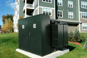
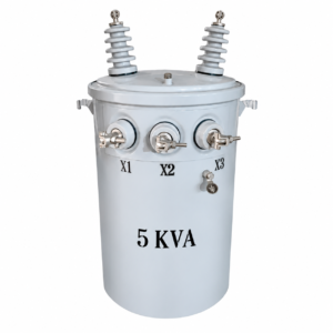
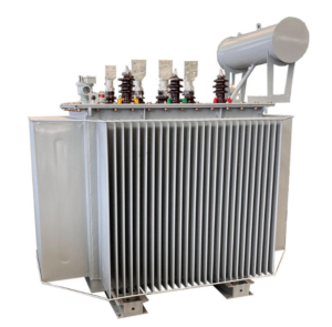
For a distribution-scale package, Zisheng Electric’s oil-immersed distribution transformer page provides a product starting point. Larger substation duties may call for the 35–46 kV power transformer or 110–115 kV power transformer range, subject to the actual project specification. These product pages do not replace a project-specific short-circuit assessment.
Discuss the evidence with Zisheng Electric
A useful transformer short-circuit withstand evidence package starts with the drawings, data sheets, load list, technical specification, single-line diagram, grid parameters, environmental conditions and installation-site conditions. Send the fault study, protection-clearing assumptions and any utility interface document available, and identify which values remain provisional. Zisheng Electric can then relate the offered transformer configuration and product range to the required evidence and agree the review points before fabrication. Our engineering team will review the requirements and respond to project inquiries within 24 hours.
About ZISHENG ELECTRICAL
Zisheng are a professional 19+ years manufacturer in producing Oil-Immersed Transformers, Compact Substation, Pad Mounted Transformers, Pole Mounted Transformers and Dry Type Transformers. We own the certificates of ISO/CE/IEC 60076 and TUV Rheinland.
Transformers undergo rigorous FAT and type testing, support voltage/capacity customization. Welcome to consult for Catalog and Product. you can contact us at email [email protected].