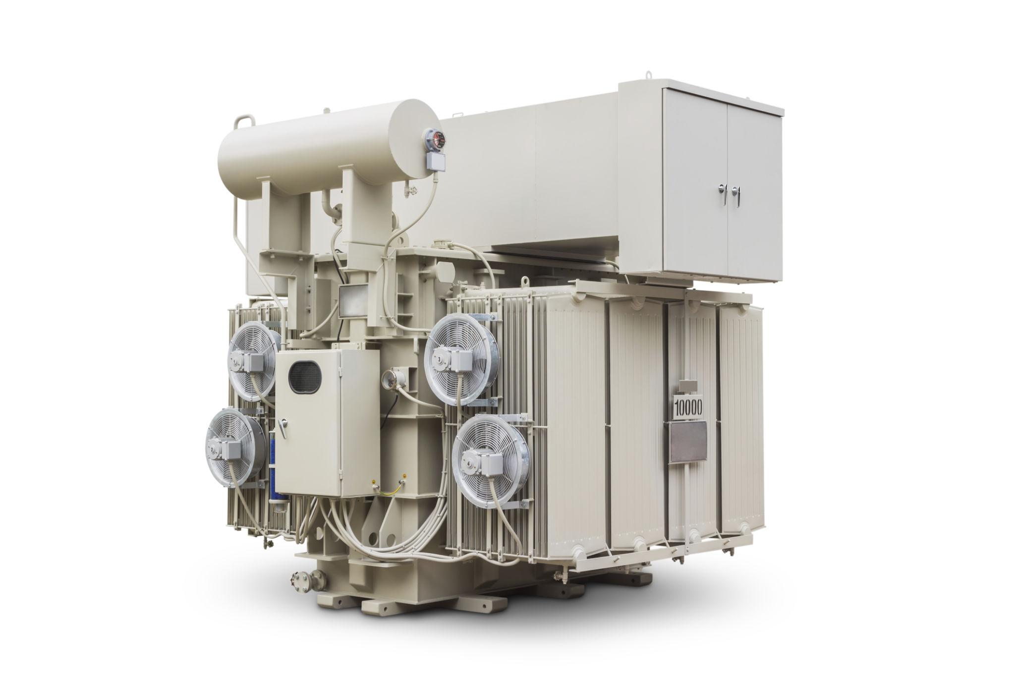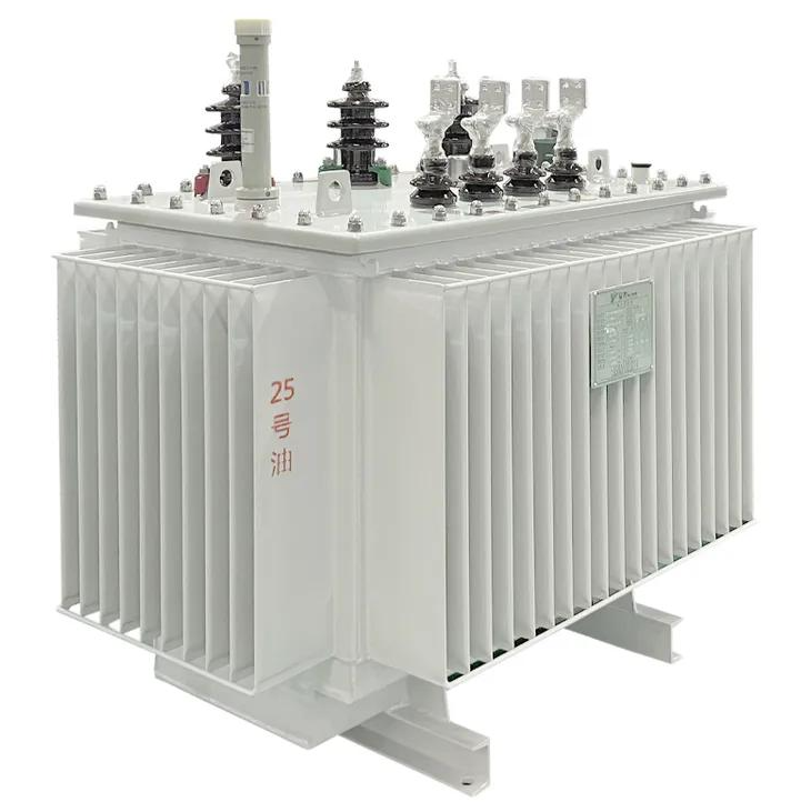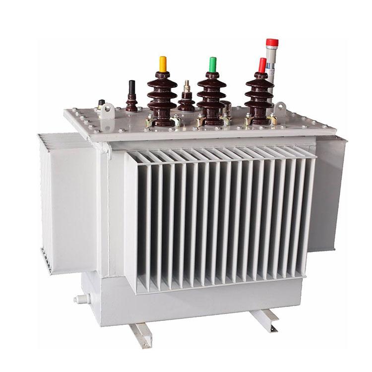

The 110kV / 115kV Power Transformer is a high-voltage oil-immersed transformer designed for power transmission, substation and large-scale industrial applications. It is used to step up or step down electrical energy between high-voltage transmission networks and medium-voltage distribution systems. The transformer can be engineered according to project requirements for rated capacity, voltage ratio, impedance, vector group, tap range, cooling system, insulation level and installation conditions.
The 110kV / 115kV Power Transformer is a high-voltage oil-immersed transformer designed for power transmission, substation and large-scale industrial applications.
It is used to step up or step down electrical energy between high-voltage transmission networks and medium-voltage distribution systems. The transformer can be engineered according to project requirements for rated capacity, voltage ratio, impedance, vector group, tap range, cooling system, insulation level and installation conditions.
Typical applications include:
The design can be supplied according to IEC, IEEE/ANSI, GB or customer-specific technical specifications.
| Parameter | Typical Specification |
|---|---|
| Product Type | Oil-Immersed Power Transformer |
| Rated Voltage | 110kV / 115kV |
| Rated Capacity | 10MVA–240MVA or customized |
| Frequency | 50Hz / 60Hz |
| Phase | Three Phase |
| High Voltage | 110kV / 115kV |
| Medium Voltage | 6.3kV / 10kV / 10.5kV / 11kV / 13.8kV / 33kV / 34.5kV or customized |
| Low Voltage | 0.4kV / 0.415kV or customized where applicable |
| Cooling | ONAN / ONAF / OFAF / ODAF |
| Tap Changer | OLTC / Off-Circuit Tap Changer |
| Tap Range | Typically ±8×1.25%, ±10×1.25% or customized |
| Vector Group | Dyn11 / YNd11 / YNd1 / customized |
| Winding Material | Copper / Aluminum |
| Insulating Medium | Mineral Transformer Oil / Ester Fluid |
| Tank Type | Conservator / Sealed Tank |
| Installation | Outdoor / Indoor Substation |
| Insulation | Oil-Paper Insulation System |
| Standard | IEC 60076 / IEEE / ANSI / GB or customized |
| Altitude | ≤1000m standard / customized |
| Ambient Temperature | Customized according to project |
| Lightning Impulse | According to insulation coordination |
| Impedance | Project-specific |
| Neutral | Solidly grounded / resistance grounded / customized |
Note: Rated capacity, impedance, insulation level, tap range and cooling arrangement should be finalized according to the customer’s technical specification rather than using one fixed value for every 110kV/115kV transformer.
The transformer can be manufactured with different voltage combinations according to grid requirements.
For utility and EPC projects, the HV/MV voltage ratio, neutral arrangement, vector group and grounding method should be confirmed during technical design.
Typical capacity ranges include:
Custom capacity available according to project requirements.
For large transmission and substation projects, higher-capacity transformers can be engineered according to system load, short-circuit level, transportation limitations and installation conditions.
The transformer uses a high-quality laminated silicon-steel core designed to reduce no-load losses and magnetizing current.
The core structure is optimized to:
The high-voltage winding is designed specifically for 110kV/115kV insulation requirements.
The winding structure can be optimized for:
For high-voltage transformers, winding and insulation design are critical because IEC 60076-3 specifies dedicated dielectric requirements for transformers in this voltage range.
The medium- and low-voltage windings are designed according to the required output voltage and load characteristics.
Copper or aluminum conductors can be selected according to:
The transformer uses an oil-paper insulation system consisting of:
The insulation system is designed to withstand:
For the 72.5kV–170kV equipment range, IEC 60076-3 includes full-wave lightning impulse and applied-voltage tests among the applicable dielectric requirements.
Different cooling configurations are available depending on transformer capacity.
Oil Natural Air Natural
Natural circulation of transformer oil and air.
Suitable for standard operating conditions and lower-capacity transformers.
Oil Natural Air Forced
Natural oil circulation with forced-air cooling.
Suitable for higher-capacity transformers and increased loading requirements.
Oil Forced Air Forced
Forced oil circulation combined with forced-air cooling.
Oil Directed Air Forced
Directed oil circulation and forced-air cooling for high-capacity transformers.
Cooling systems can be configured with:
The 110kV/115kV transformer can be equipped with an On-Load Tap Changer (OLTC) to regulate the output voltage while the transformer is energized.
Typical configuration:
HV winding + OLTC
Typical tap ranges may include:
The actual tap range and tap position depend on the grid voltage regulation requirements.
The transformer tank is manufactured from high-strength steel and designed to withstand:
The tank can be supplied with:
Depending on the project requirements, the transformer can be equipped with:
The transformer can incorporate multiple protection systems to improve operational safety.
Detects gas accumulation and oil flow caused by internal transformer faults.
Provides rapid pressure release in case of abnormal internal pressure.
Monitors:
Provides continuous monitoring of transformer oil level.
The OLTC can be equipped with dedicated protection and monitoring devices.
Designed for 110kV and 115kV transmission and substation applications with appropriate insulation coordination and dielectric testing.
Optimized magnetic core and winding design help reduce no-load and load losses.
Mechanical strength of windings and clamping structures is designed to withstand the electromagnetic forces generated during short-circuit conditions.
Multiple cooling configurations are available for different capacity and loading requirements.
HV, MV, LV, tap range and vector group can be customized according to the grid specification.
High-quality core materials, insulation components, transformer oil and sealing systems support reliable long-term operation.
Design parameters can be coordinated with different international grid standards and project specifications.
Each transformer should undergo the required routine tests before shipment.
Typical tests include:
IEC 60076-1 identifies winding resistance, ratio/phase displacement, short-circuit impedance/load loss, no-load loss/current and dielectric tests among the routine testing framework.
For high-voltage projects, the purchaser can additionally specify tests such as partial discharge, frequency response analysis (FRA), temperature-rise testing, acoustic/noise testing and short-circuit withstand testing, depending on the project specification.
For utility and EPC projects, additional testing can be arranged according to the purchase specification.
IEC 60076 testing is generally divided into routine, type and special testing categories, with special tests agreed between purchaser and manufacturer.
The transformer can be designed and tested according to:
IEC 60076-3 specifically addresses insulation requirements and dielectric tests for power transformers.


Used in transmission and distribution substations for voltage transformation and grid interconnection.
Suitable for connecting generating units to high-voltage transmission networks.
Can be used in large-scale:
Suitable for:
Suitable for large:
Zisheng can customize the transformer according to project-specific technical requirements.
Because 110kV/115kV transformers can be large and heavy, transportation engineering should be considered during the design stage.
Typical shipping preparation includes:
For large transformers, the manufacturer can provide:
Depending on the contract, the manufacturer can provide:
20+ Years Transformer Manufacturing Experience
Customized 110kV / 115kV Transformer Design
Factory Direct Manufacturing
IEC / IEEE / GB Standards
Complete Factory Testing
OEM / ODM Available
EPC Project Support
Global Export Experience
For an accurate quotation, customers are recommended to provide:
Zisheng are a professional 19+ years manufacturer in producing Oil-Immersed Transformers, Compact Substation, Pad Mounted Transformers, Pole Mounted Transformers and Dry Type Transformers. We own the certificates of ISO/CE/IEC 60076 and TUV Rheinland.
Transformers undergo rigorous FAT and type testing, support voltage/capacity customization. Welcome to consult for Catalog and Product. you can contact us at email [email protected].
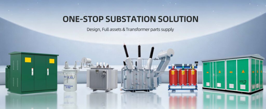
The 110kV / 115kV Power Transformer is designed for high-voltage power transmission and substation applications where reliable voltage transformation, stable grid operation and long-term continuous service are required.
This product case represents a typical high-voltage substation project in which customized oil-immersed power transformers are supplied for transforming transmission-level voltage to medium-voltage distribution networks.
The solution is suitable for utility companies, EPC contractors, industrial facilities, mining projects and renewable-energy developers.
| Item | Project Information |
|---|---|
| Project Type | High-Voltage Substation |
| Transformer Type | Three-Phase Oil-Immersed Power Transformer |
| Rated Voltage | 110kV / 115kV |
| Rated Capacity | 40–120 MVA, project dependent |
| Frequency | 50Hz / 60Hz |
| HV Side | 110kV / 115kV |
| MV Side | 11kV / 13.8kV / 33kV / 34.5kV |
| Cooling | ONAN / ONAF |
| Tap Changer | OLTC |
| Vector Group | Dyn11 / YNd11 / Customized |
| Installation | Outdoor Substation |
| Application | Grid Transmission & Distribution |
| Testing | Factory Routine Testing + FAT |
| Standards | IEC 60076 / Customer Specification |
Note: Actual project parameters are determined according to the approved technical specification. The above data represents a typical project configuration and should not be interpreted as a fixed standard product specification.
The customer required a high-capacity transformer solution for a new high-voltage substation.
The project required the transformer to:
Because the project involved high-voltage grid connection, the transformer design had to be coordinated with the customer’s grid configuration, protection system, insulation coordination and substation layout.
The customer requested a transformer with:
Zisheng engineers developed a customized transformer design based on the customer’s technical specification.
The engineering process included:
Technical Specification Review
↓
Electrical Design
↓
Insulation Coordination
↓
Winding Design
↓
Core Design
↓
Thermal Design
↓
Tank & Mechanical Design
↓
Protection & Control Design
↓
Manufacturing
↓
Factory Testing
↓
FAT
↓
Packing & Shipping
The HV winding was designed specifically for the 110kV/115kV system.
The design considered:
The insulation system was designed according to the specified high-voltage requirements.
The MV winding was designed according to the customer’s required distribution voltage.
Possible outputs included:
11kV
13.8kV
33kV
34.5kV
The winding design was optimized for the required rated current, losses and short-circuit withstand capability.
The transformer uses a high-quality laminated grain-oriented silicon-steel core.
The core design focuses on:
The core is manufactured and assembled according to the approved engineering drawings.
The transformer can use an ONAN/ONAF cooling system according to load and capacity requirements.
Under normal operating conditions, natural oil circulation and natural air cooling can be used.
When transformer loading increases, forced cooling equipment can automatically operate to improve heat dissipation.
The cooling system can include:
Because the transformer is connected to a high-voltage grid, voltage fluctuation can affect downstream loads.
An On-Load Tap Changer (OLTC) can therefore be incorporated into the transformer.
The OLTC allows voltage regulation without interrupting transformer operation.
The system can provide:
The transformer was equipped with a comprehensive protection and monitoring system.
For advanced projects, monitoring data can be integrated into the customer’s SCADA/substation automation system.
The transformer was manufactured through controlled production processes covering:
Precision cutting and assembly of silicon-steel laminations.
Controlled winding processes ensure dimensional accuracy and mechanical strength.
The insulation system is carefully assembled to maintain required dielectric performance.
The core and windings are assembled and mechanically clamped.
The tank is fabricated, welded, inspected and surface treated.
Radiators, bushings, conservator, OLTC, protection devices and control equipment are installed according to approved drawings.
Before final oil filling, the transformer insulation system is subjected to appropriate drying and vacuum treatment.
The process helps remove:
Transformer oil is processed using appropriate filtration and vacuum treatment equipment before final filling.
This is particularly important for high-voltage transformer insulation reliability.
Before delivery, the transformer undergoes a complete routine test program.
Testing can include:
The results are documented in the factory test report.
For the project, customer or third-party inspection can be arranged before shipment.
A typical FAT procedure includes:
Document Review
↓
Visual Inspection
↓
Routine Electrical Testing
↓
Protection & Control Testing
↓
OLTC Testing
↓
Cooling System Testing
↓
Test Result Review
↓
Final Inspection
↓
Customer Acceptance
This provides the purchaser with additional confidence before the transformer leaves the factory.
After factory acceptance, the transformer is prepared for international transportation.
Depending on transformer size and logistics requirements, the shipping configuration may include:
For large transformers, transportation may use:
Heavy Truck → Port → Breakbulk / Project Cargo Vessel → Destination Port → Special Transport Vehicle → Project Site
Moisture protection, waterproof protection and shock protection are applied during packing.
After arrival at the project site, installation generally includes:
All installation procedures should follow the manufacturer’s approved installation and commissioning documentation.
The customized 110kV/115kV transformer solution provides the project with:
Designed for high-voltage transmission and substation applications.
OLTC enables voltage adjustment under energized conditions where specified.
Optimized core and winding design helps control no-load and load losses.
The winding and clamping structure are engineered for the specified short-circuit conditions.
Multiple monitoring and protection devices support safe transformer operation.
Electrical, mechanical, insulation and monitoring parameters can be customized according to the customer’s requirements.
This transformer solution can be applied to:
110kV / 115kV High-Voltage Design
Customized MVA Capacity
OLTC Voltage Regulation
ONAN / ONAF Cooling
IEC 60076-Based Testing
Complete Factory Routine Testing
Customer-Witnessed FAT Available
Customized Protection & Monitoring
Export Seaworthy Packing
Global EPC Project Support
For a similar 110kV/115kV transformer project, customers can provide:
Capacity: ___ MVA
HV: 110kV / 115kV
MV: ___ kV
Frequency: 50Hz / 60Hz
Vector Group: ___
Impedance: ___ %
Tap Range: ___
OLTC: Yes / No
Cooling: ONAN / ONAF / OFAF / ODAF
Quantity: ___ units
Project Location: ___
Based on these parameters, Zisheng can develop a custom transformer design, technical datasheet, GA drawing, testing plan and commercial quotation for the project.
A 110kV / 115kV Power Transformer is a high-voltage oil-immersed transformer designed to transfer electrical energy between transmission and medium-voltage networks.
It is commonly used in:
The transformer can be customized according to capacity, voltage ratio, impedance, vector group, cooling system, tap range and insulation requirements.
The main difference is the rated system voltage for which the transformer is designed.
A 110kV transformer is commonly used in transmission systems based on a 110kV nominal voltage, while a 115kV transformer is commonly used in systems using a 115kV nominal voltage.
The actual design must consider:
The final rated voltage should therefore be determined according to the customer’s grid specification rather than simply selecting 110kV or 115kV based on nominal voltage.
Typical capacities include:
Higher capacities can also be engineered for large utility and power-generation projects.
Capacity is fully customizable according to the customer’s load and grid requirements.
Common configurations include:
Three-winding configurations are also available, such as:
Other voltage combinations can be customized.
Yes.
The 110kV / 115kV power transformer is normally supplied as an oil-immersed transformer using an oil-paper insulation system.
Available insulating fluids may include:
The insulating medium can be selected according to project requirements and applicable standards.
Different cooling systems can be supplied according to transformer capacity.
Oil Natural Air Natural.
Oil Natural Air Forced.
Oil Forced Air Forced.
Oil Directed Air Forced.
Large-capacity transformers may use forced oil circulation and forced-air cooling to maintain acceptable temperature rise under high loading conditions.
Yes.
An On-Load Tap Changer (OLTC) can be installed for applications requiring voltage regulation while the transformer is energized.
Typical tap ranges include:
The OLTC can include:
Typical vector groups include:
The appropriate vector group depends on the customer’s grid configuration, grounding system and parallel-operation requirements.
Yes.
The transformer can be customized in almost every major electrical and mechanical parameter.
Customization includes:
The transformer can be designed and tested according to:
For 110kV/115kV applications, the insulation and dielectric testing requirements are coordinated with the applicable high-voltage transformer standard and project insulation level.
Each transformer undergoes the required factory routine tests before delivery.
Typical tests include:
A complete Routine Test Report can be provided to the customer.
Yes.
Depending on the applicable standard and project specification, testing can include:
The required test levels are determined by the specified insulation coordination and customer requirements.
Yes.
For major utility and EPC projects, Factory Acceptance Testing (FAT) can be arranged.
Customer or third-party inspectors can witness selected tests according to the approved Inspection & Test Plan (ITP).
A typical FAT process is:
Document Review → Visual Inspection → Routine Testing → Functional Testing → Special Testing → Test Report Review → Final Acceptance
Yes.
The transformer can be designed for utility-scale photovoltaic projects.
Typical configuration:
Solar PV → Inverter → MV Collection System → 110/115kV Transformer → Grid
Common configurations include:
33kV / 110kV
34.5kV / 115kV
The transformer can be customized for:
Yes.
The transformer can be used as the main grid interconnection transformer for wind farms.
Typical system:
Wind Turbines → MV Collector Network → 110/115kV Transformer → Transmission Grid
The design can be customized according to the wind farm’s installed capacity, collector voltage and grid-connection requirements.
Yes.
110kV/115kV transformers are suitable for large mining and mineral-processing projects.
Applications include:
The transformer can supply 33kV, 11kV or other medium-voltage distribution systems within the mining site.
Special designs can be provided for:
Yes.
The transformer can be customized for harsh environmental conditions, including:
Possible adaptations include:
Yes.
High-altitude installation can be accommodated during design.
The design may need to consider:
The customer should provide the actual installation altitude so the transformer can be properly engineered.
The transformer can be equipped with:
Protection configuration can be customized according to the utility or EPC protection philosophy.
Yes.
Optional online monitoring systems can include:
Communication can be integrated with the customer’s control or SCADA system where required.
Large transformers require project-specific transportation planning.
Possible shipping configurations include:
For large units, the manufacturer can provide:
Yes.
Export packing can be arranged for international projects.
The shipping package can include:
The shipping method can be coordinated according to the destination country, port and project logistics requirements.
Depending on the contract, the documentation package can include:
Additional documents can be supplied according to EPC or utility requirements.
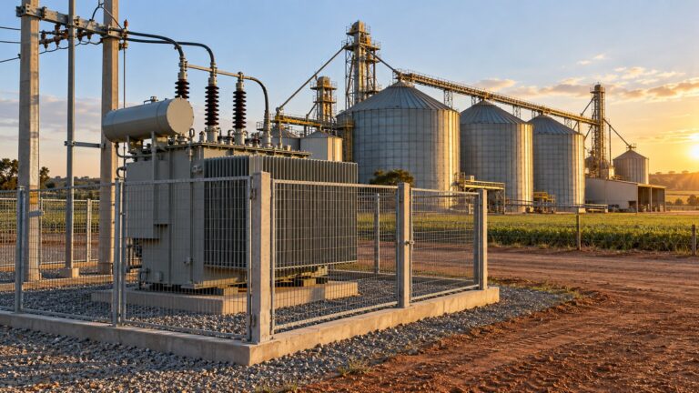
A procurement-focused review of transformer overfluxing in African industrial plants with captive generation. Compare voltage-frequency cases, define event durations and obtain equipment-specific...
 Project
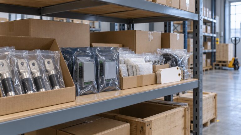
A practical transformer spare parts schedule for African EPC projects: verify interchangeability, storage, documentation and final handover.
 Technical Guidance
Compare seasonal transformer operating states using energized hours, guaranteed losses, essential loads and a transparent one-unit versus two-unit calculation.