Transformer Load Shedding and Restoration Interface for African Industrial Plants
Zisheng Electric often sees an industrial transformer specified carefully while the operating sequence around it remains implicit. For an African plant with a utility supply, standby generation and large motors, the transformer load shedding interface is a project decision: which feeders disconnect, who commands the transfer, what may restart, and what evidence permits the next step? A nameplate kVA alone cannot answer those questions. The EPC contractor, owner, generator supplier and transformer manufacturer need one agreed sequence before protection settings and control drawings are frozen.
This guide develops a practical interface schedule for a plant with essential services and several motor-driven processes. It deliberately avoids assuming a national grid voltage, frequency or utility rule: each site must supply its approved connection conditions. The same logic can be adapted to mining, water treatment, cement, food processing or port infrastructure, but the feeder priorities and restart limits will differ. The goal is a usable procurement and commissioning record, not a generic promise that a transformer can carry every load after an outage.
Define the transformer load shedding interface at the single-line boundary
Start with the actual single-line diagram. Identify the utility incomer, transformer high- and low-voltage breakers, bus ties, generator breaker, automatic transfer arrangement and every feeder that remains energized after loss of the normal source. Mark the protection and control ownership at each boundary. If the generator backs up only one section, a bus tie permissive matters as much as the transformer’s rating. If two transformers normally share a bus, loss of one unit changes both loading and short-circuit conditions.
Represent the operating states explicitly: normal utility supply, utility loss, emergency generation, utility return, planned maintenance and abnormal breaker failure. For each state, record the source that can energize each bus, the allowable loads and the required isolation. A sequence that works in normal operation can fail during maintenance when a normally open tie is closed. The interface schedule should be reviewed against the owner’s switching procedure and the utility’s approved point-of-connection requirements. Neither should be inferred from a country label.

Put command and feedback on the same drawing
A trip command without a verified open indication is an incomplete load-shed function. Record the initiating signal, output contact, destination device, feedback point, local/remote selector position, loss-of-control-power behavior and event timestamp. For critical feeders, decide whether a failed indication blocks transfer or triggers a manual decision. The owner should name the party who can override each interlock and the conditions under which that override is permitted. This is especially relevant where generator and utility controls are supplied under separate contracts.
Review the transformer’s auxiliary supply independently. Cooling fans, monitoring, tap-changer motors and control circuits may have different sources and ride-through requirements. Zisheng Electric’s article on transformer auxiliary power specification outlines why the AC and DC interfaces need to be fixed before panel drawings and cable schedules are released.
Classify loads by process consequence and electrical restart behavior
“Critical” is a process label, not a complete electrical category. Fire and safety services may have mandatory supply arrangements under the approved project design, but an essential process pump can still impose a large starting current. Separate life-safety, equipment-preservation, controlled shutdown and production loads. Then describe each load electrically: running kW and kvar, starting method, inrush or acceleration current, minimum voltage during start, permissible interruption, restart delay and the consequences of simultaneous start.
Ask the process engineer for an actual load list with motor duty, not just an installed-kW total. A variable-speed drive may restart differently from a direct-on-line motor and can introduce input harmonics; a motor with high inertia may draw elevated current longer than a small pump. Capacitor banks, UPS rectifiers and other electronic loads also influence re-energization. Their behavior must be obtained from vendors or measured where the facility already exists. A guessed diversity factor should never become the transformer loading guarantee.
| Interface decision | Evidence to request | Engineering consequence | Release criterion |
|---|---|---|---|
| Essential feeder priority | Approved process criticality and load list | Defines what survives utility loss | Owner signs the bus-by-bus priority schedule |
| Generator pickup blocks | Generator step-load and frequency response data | Prevents an excessive single load step | Control sequence matches the generator study |
| Motor restart groups | Starting current, acceleration time and voltage-dip study | Limits voltage depression and transformer heating | Sequential start permissives are tested |
| Transformer loading window | Rated data, cooling state, ambient profile and approved loading study | Sets sustained and temporary loading decisions | Owner approves alarm, shed and recovery thresholds |
| Utility return | Approved synchronizing/transfer philosophy and utility interface | Avoids unintended parallel operation or reverse feed | Interlocks and indications pass functional tests |
The table is a decision register, not universal settings. Actual pickup blocks and delays are derived from the generator supplier, protection study, motor data and site’s operating philosophy. A useful drawing revision includes the source document and owner of every threshold. If the project lacks those inputs, record the item as open and prevent a premature control-logic sign-off.
Model the first seconds after supply loss
On loss of the utility source, protection must distinguish a genuine upstream outage from a local fault. The sequence normally involves voltage detection, breaker opening, confirmation of isolation, generator start or alternative-source availability, bus energization and staged load pickup. The exact order depends on the protection philosophy and equipment. The transformer may be energized from a generator before any process load is restored, so magnetizing inrush and generator voltage recovery belong in the same study.
Public U.S. Department of Energy guidance on grid-forming inverter restoration identifies transformer, cold-load and motor inrush as significant restoration duties. Its equipment context differs from a conventional industrial generator, and it is not an African utility requirement. The project study must use its own transformer, generator and load data. The contractor should examine worst credible cases including a cold transformer, a warm process with automatic restart enabled, loss of one generator set and delayed return of a bus section.
Define a failure response for every stage. If an incomer fails to open, block the generator close command and raise a clear alarm. If a generator does not accept its first block, shed or inhibit the next group rather than repeatedly attempting the same start. If the low-voltage bus does not reach the required voltage band, hold motor restarts and let the operator inspect the condition. Avoid sequences that depend solely on a timer without checking breaker, voltage and source indications.
Set a transformer loading decision without assuming spare capacity
Transformer thermal capability depends on losses, cooling equipment, initial temperature, ambient conditions and loading duration. A spare kVA margin on a schedule is not a substitute for a loading assessment. Where temporary overload is contemplated after loss of a parallel unit, obtain the manufacturer’s guaranteed data and an approved thermal loading study. State the alarm, first load-shed and emergency trip criteria in terms of measured and calculated quantities that the control system can actually access.
Check the physical cooling state during an outage. Forced-cooling fans may be unavailable if the auxiliary supply is lost, even when the transformer remains energized. The site should distinguish a fan-failure alarm from a transformer-protection trip and set a response window consistent with the approved study. Cooling duty, ambient temperature and site altitude are project inputs; an “African climate” assumption cannot replace a surveyed design envelope. For broader procurement questions on generator and motor duty, see Zisheng Electric’s industrial transformer procurement guide; project values still require verification.
Each operating limit should have a decision owner. A controls contractor can implement the thresholds, but the owner and engineer must approve the permitted risk and load priority. The transformer supplier can provide loss and thermal data but should not be asked to certify an undefined plant-wide restoration sequence. Document the study revision cited by the controls logic, especially when late process changes add motors or alter duty cycles.
Design motor restart groups for the actual process
Divide motors into groups whose starts can be supervised. Consider lubrication and cooling prerequisites, pressure equalization, valve position and the minimum time since a previous trip. A pump that must start early for equipment preservation may still need a soft starter, drive or dedicated delay to avoid simultaneous acceleration with another large load. The transformer winding and generator both experience the resulting current and voltage changes.
Reconnection after a short interruption can differ from a cold start. Some motors may coast, drives may retain DC-bus energy for a limited period, and automatic restart logic may issue overlapping commands. The EPC team should obtain the motor-control-center schedule and vendor restart settings. Test the transition from each operating mode rather than only the ideal sequence from a completely de-energized plant. If the site has harmonic-producing drives, include the measured or specified harmonic spectrum in the transformer loss and thermal review; do not infer a harmonic allowance from kVA alone.

State what the operator sees. A screen should identify the blocked feeder, source status, reason for inhibition and manual-release authority. A bare “load shed active” alarm is of limited value during a plant restart. The recorded event sequence should allow engineers to compare actual voltage and current recovery against the study and refine settings within the approved change-control process.
Control the utility return and avoid unplanned parallel operation
The return of grid voltage is not permission to close every breaker immediately. Determine whether transfer is open-transition, closed-transition or manual, subject to the approved utility and site requirements. For open transition, confirm isolation before a source change and consider the process interruption. For closed transition, synchronizing, protection and utility approval become central; do not assume this function exists because a controller has a menu option for it.
After the normal source returns, staged reconnection should follow a defined voltage-stability and feeder-priority check. Coordinate tap-changer controls where applicable so source changes do not create avoidable voltage excursions. Confirm which alarms reset automatically and which require inspection. For replacement or maintenance outages, the related transformer replacement outage planning guide addresses access and switching interfaces that often constrain the restoration schedule.
Use a commissioning script that proves the interface
A factory review can verify terminal assignments, logic diagrams, I/O lists and simulated alarms. It cannot prove the full plant response without site devices. Build a site-acceptance script around the actual single-line diagram. Witness loss of the normal-source indication, breaker interlocks, generator available/unavailable states, staged feeder pickup, inhibited motor starts and return-to-normal operation. Inject credible sensor and feedback failures to verify that unsafe close commands are blocked.
Capture time-stamped evidence from relays, control PLC, SCADA, breaker auxiliary contacts and portable meters. For every test, record the initial state, trigger, expected indications, measured response, observed result, deviation and owner of corrective action. Avoid claiming that a simulation proves generator step-load performance; where live testing is constrained, document the remaining commissioning gap and the agreed operational restriction. Revisions to the sequence should be traced into the operating manual and training material.

Freeze a clear procurement interface
When issuing an RFQ, include the duty states, load schedule, generator arrangement, specified control and indication points, protection study responsibilities, cooling auxiliary sources and required commissioning evidence. Distinguish transformer supply from EPC integration: the transformer manufacturer provides guaranteed electrical data, terminals, alarms and drawings within its scope; the EPC team integrates the source transfer, load-shedding commands and plant controls. A responsibility matrix prevents both omission and duplicate scope.
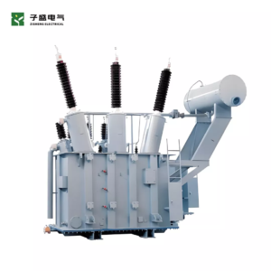
Zisheng Electric can evaluate an oil-immersed transformer or a substation transformer against the approved duty and interface schedule. For a useful review of the transformer load shedding interface, send drawings, transformer and generator datasheets, the complete load list, technical specifications, the latest single-line diagram, verified grid parameters, environmental conditions and installation-site constraints. Include the proposed operating states, motor starting data and current control-logic revision. Our engineering team will review the requirements and respond to project inquiries within 24 hours.
About ZISHENG ELECTRICAL
Zisheng are a professional 19+ years manufacturer in producing Oil-Immersed Transformers, Compact Substation, Pad Mounted Transformers, Pole Mounted Transformers and Dry Type Transformers. We own the certificates of ISO/CE/IEC 60076 and TUV Rheinland.
Transformers undergo rigorous FAT and type testing, support voltage/capacity customization. Welcome to consult for Catalog and Product. you can contact us at email [email protected].