
Transformer Auxiliary Power Specification for Remote African Projects
Zisheng Electric treats the transformer auxiliary power specification as part of the project’s operating plan. The main windings may be ready to carry load while the cooling controls, tap drive, alarm circuits or cabinet heaters still lack a dependable supply. For a remote African industrial project, discovering that gap during commissioning can leave equipment waiting for a small component or an unresolved interface long after the transformer has arrived.
The useful starting question is simple: which functions must remain available before energization, during a supply interruption and after power returns? This project-planning guide follows those three conditions. It does not assume a common African grid voltage, a particular outage frequency or a standard battery autonomy. Those values belong to the confirmed site design basis and the equipment actually offered.
Build the transformer auxiliary power specification around operating states
An auxiliary-load list should identify a function, its source and the consequence of losing it. A list containing only a total number of kilowatts is insufficient. A cooling motor, an electronic monitor and a trip circuit can have very different starting demands, interruption tolerances and restoration requirements. They may also sit in different supply packages, even when their cables terminate in the same transformer marshalling cabinet.
Define the boundary between transformer and station supplies
Mark who supplies each feeder, protective device, cable, terminal and source-failure alarm. The transformer supplier may provide a local distribution arrangement while the EPC contractor provides its incoming supply. Protection and breaker operating circuits may belong to separate panels. An interface drawing should make those boundaries visible, including the point at which voltage must meet the accessory manufacturer’s requirements.
Record installed equipment rather than assuming every transformer has forced cooling or a motor-operated tap changer. Naturally cooled equipment can have a smaller auxiliary package, but monitoring, control or preservation functions may still need power. Conversely, a larger transformer can have several cooling stages and separately supplied control systems. The review must follow the selected design.
Use five states in the project review
Review delivery and storage, pre-energization commissioning, normal operation, loss of the normal source, and restoration. Add maintenance isolation where it creates another arrangement. For each state, ask what remains live, what stops, what indication survives and who authorizes the next step. This exposes dependencies that a normal-running single-line diagram can hide.
| Auxiliary function | Supply information to obtain | Question during source loss | Evidence to request |
|---|---|---|---|
| Cooling fans or pumps, when fitted | Running input, starting demand, number operating together and permissible supply range | What loading remains acceptable when a cooling stage is unavailable? | Manufacturer’s cooling-duty limits and approved staging logic |
| Tap-drive motor and controls | Separate motor, control and heater requirements for the offered mechanism | What indication and recovery procedure apply if supply fails during an operation? | Order-specific circuit diagrams and mechanism instructions |
| Protection and breaker operating circuits | Source arrangement, duty cycle, circuit supervision and required operating sequence | Can the approved protection scheme still detect and clear the relevant condition? | Protection design and end-to-end verification plan |
| Monitoring and communications | Power input, restart behavior and data-retention requirements | Will the operator receive a meaningful supply-failure indication? | Alarm matrix and power-loss recovery demonstration |
| Cabinet preservation equipment | Heater and control requirements, including storage supply | How is the cabinet preserved during a prolonged outage? | Manufacturer-approved preservation and inspection plan |
Before energization: remove circular supply dependencies
Suppose the normal auxiliary feeder is connected to a bus that becomes live only after the main transformer is energized. That arrangement needs a specific first-energization review. Which controls, indications and protection functions are required before the main breaker can close? Where does their power come from? The answer may involve an independent station supply, an approved temporary source or another engineered arrangement. It cannot be left as an informal commissioning workaround.
Temporary power needs the same clarity about voltage, frequency, earthing, protection and isolation as the permanent interface. Identify its connection point and the controlled transition to the permanent supply. Prevent an unintended connection between independent sources. The project’s qualified electrical team should approve the arrangement and switching procedure before anyone connects temporary equipment.
Match accessory data, not just the main transformer rating
The accessory schedule should state AC or DC, phases where applicable, voltage and frequency, permissible variation and demand. Obtain starting or operating duty as well as continuous consumption. A main transformer nameplate does not establish the correct supply for every installed accessory. Confirm those details against order-specific drawings before the EPC team releases its auxiliary distribution panel.
A useful manufacturer example is the TAPMOTION ED technical-data document, which treats motor, control and heating circuits separately. Its order forms distinguish supply arrangements for these functions. This illustrates why one generic “auxiliary voltage” entry can be inadequate. It does not establish the requirements of a different mechanism or imply that this device is included in a Zisheng Electric offer.
During operation: check the source against actual demand
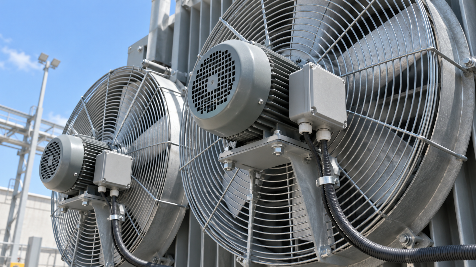
Start with the confirmed load schedule and the equipment duty. Account for which cooling groups can run together, which motors may start together, and which control loads must remain available while that happens. The upstream source, feeder protection, cable route and terminal voltage all belong in the assessment. A feeder sized only from a convenient aggregate running load may overlook a demanding transition.
For a long cable run between the station-services board and an outdoor transformer, check voltage at the accessory terminals under the relevant conditions. Ask the designer to include source behavior and starting demand, not merely the cable’s continuous-current capability. Where a generator supplies station services, its response and the load sequence also require review. Do not substitute a blanket cable-size recommendation for that calculation.
Cooling availability must connect to an operating instruction
A fan-failure lamp is useful only if the operator knows its consequence. Obtain the manufacturer’s permitted loading conditions with the affected cooling stage unavailable. Tie the indication to an approved response, which may involve load reduction, inspection or another specified action. Do not assume that a transformer can retain its highest cooling-assisted rating indefinitely after its auxiliary supply disappears.
Separate commanded operation from proved operation in the signal list. A controller may request cooling without demonstrating that the required equipment has started. Agree what feedback is available, what failure it detects and how it appears in the control room. The level of supervision should follow the operating risk and the maintainability of the selected system.
At source loss: preserve the functions that matter
Loss of normal AC supply is a different event from loss of an individual auxiliary feeder. Review both. Two incoming cables do not provide independent supplies if they share the same upstream failure point. Trace the source paths far enough to understand the intended redundancy and document the common dependencies. This helps buyers compare an actual continuity arrangement with an offer that merely includes an extra terminal block.
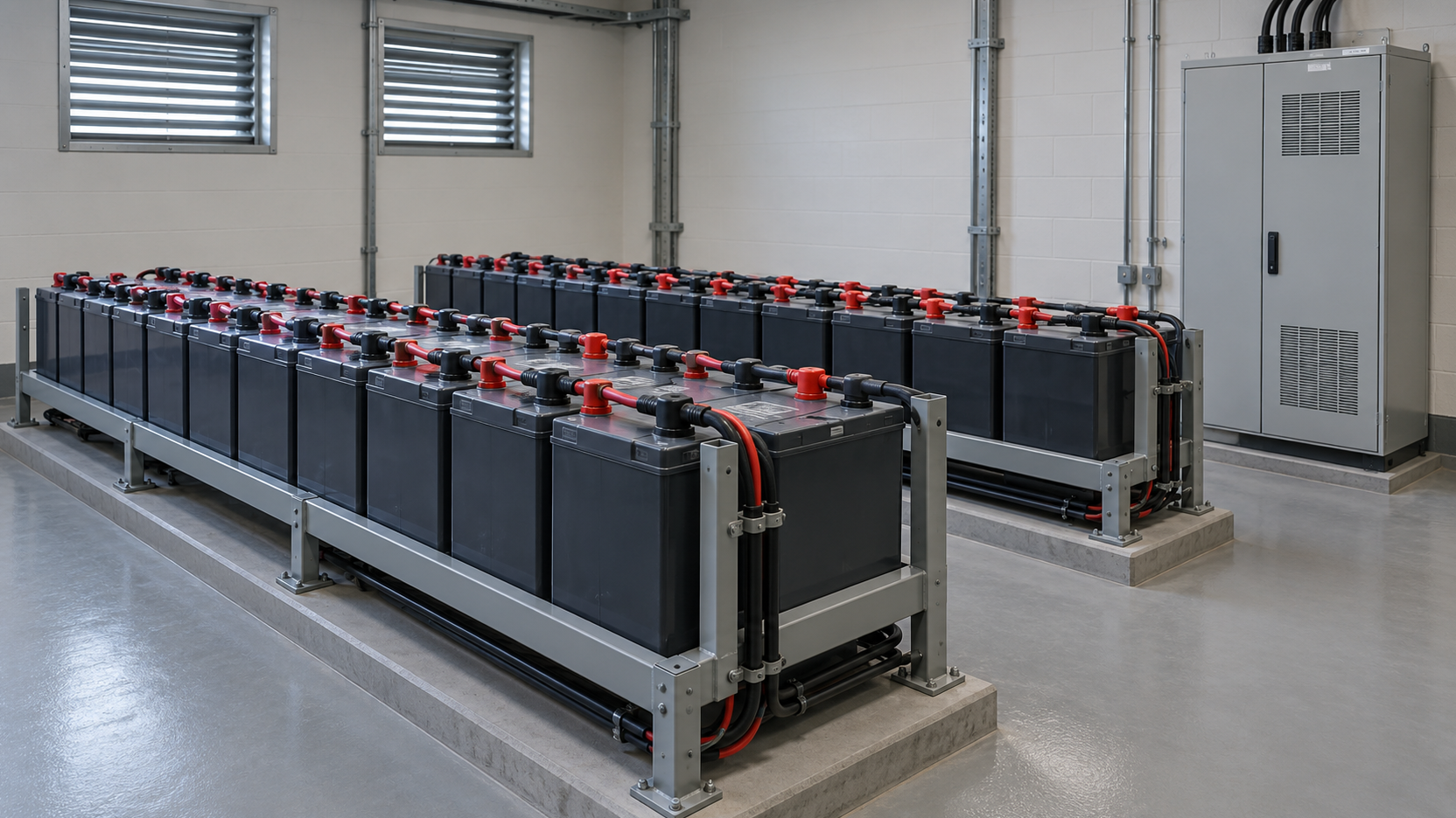
Protection, breaker operation, monitoring and communications deserve separate treatment. Where the approved station design uses batteries or a UPS, establish the loads and operating sequence that arrangement must support. Specify the required duration from the project’s restoration plan, then have the responsible designer substantiate the capacity and performance. An arbitrary autonomy figure copied from another project is not a design calculation.
Make loss of supply observable
Consider how the operator learns that a local supply has failed. An alarm generated by the same failed circuit may disappear when it is most needed. Review the indication path, supervision and remote reporting with the protection and control designer. The intention is to make the relevant loss detectable, without assuming that every accessory needs an identical backup source.
Also establish who responds when communications are unavailable. A remote site may have local staff but no specialist on that shift; another may have a nearby service team. Confirm the actual staffing and travel arrangements with the owner. Those facts determine useful local indications, spare holdings and escalation instructions more reliably than a regional label.
After restoration: control the return to service
Power returning to a panel does not prove that every function has recovered. Ask which controllers restart automatically, which settings persist, which alarms latch and which equipment requires inspection or reset. Review cooling restart with the upstream source so simultaneous motor starting does not undermine the intended recovery. Any delay or staging arrangement must remain consistent with the transformer’s required cooling duty.
Tap-drive recovery requires the instructions for the actual mechanism. Specify how an interrupted operation is detected and who may authorize subsequent action. Do not prescribe an improvised reset sequence in a general procurement article. Our mining tap-changer selection guide covers the wider control and maintenance decision; this review concerns the supply interface that allows the chosen equipment to perform its assigned function.
A hypothetical restoration review
Consider an industrial installation whose normal auxiliary feeder is unavailable while station protection remains supplied from its approved DC system. The transformer is isolated, and the owner plans to restore the auxiliary source before returning the main equipment to service. The review should confirm cabinet condition, available protection, cooling readiness, tap-drive status and control indications before the authorized switching sequence proceeds.
This is a planning example, not a report of a completed customer project. It does not establish a universal energization sequence. Its purpose is to show why supply restoration, accessory recovery and permission to energize are separate decisions with identifiable owners.
During a long outage: keep preservation in the scope
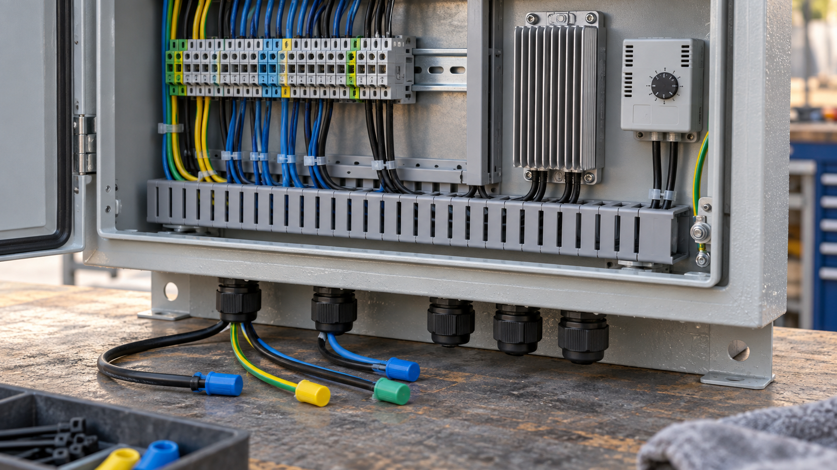
Cabinet heaters and related controls are easy to omit when attention shifts to the main circuit. Ask the manufacturer which preservation measures apply during storage, construction delays and extended isolation. Establish whether the required supply remains available when the main transformer is out of service. If it cannot be maintained, obtain an approved alternative and the inspection needed before recommissioning.
Provide measured or project-approved temperature, humidity, altitude, dust and corrosion exposure. Avoid assuming that all remote African locations are hot, dry or dusty. The equipment enclosure, cable entries and preservation arrangement must suit the actual installation. Record access restrictions and the availability of replacement components, particularly where a small heater, contactor or supply module would be difficult to obtain quickly.
Buy spares that match the installed configuration
A spare contactor with the wrong coil rating can be unusable even when its power contacts look identical. Request confirmed part numbers and applicable ratings for selected critical components, together with storage requirements and replacement instructions. Coordinate this with the owner’s broader shared spare transformer planning, while keeping accessory readiness distinct from the availability of a replacement transformer.
Close the package with demonstrations and named responsibilities
Agree the factory checks for accessory operation, local distribution, indication and simulated supply-loss behavior within the supplied package. Identify which interfaces cannot be proved until installation, such as the site’s battery system, incoming feeder performance and control-room alarm path. The inspection plan should distinguish factory evidence from integrated site verification instead of treating a component test as proof of the whole station.
Before release, reconcile the auxiliary-load list, circuit diagrams, cable schedule, alarm matrix, operating narrative and spare-parts list. Record open values with an owner and a due date. During commissioning, retain the approved settings and observed recovery behavior in the handover package. This gives the operating team a usable baseline for later changes to cooling stages, monitoring equipment or station supplies.
Send Zisheng Electric a complete auxiliary supply enquiry
For equipment such as the 10 MVA oil-immersed power transformer, review its offered auxiliary package alongside the main duty. Where a separate distribution unit is being considered for station services, the 150 kVA three-phase pad-mounted transformer is a product reference, not a sizing recommendation. Ratings, interfaces and suitability require project-specific confirmation.
To develop the transformer auxiliary power specification, send Zisheng Electric the drawings, data sheets, load list, technical specifications, single-line diagram, grid parameters, environmental conditions and installation-site conditions. Include the auxiliary source arrangement, required continuity, proposed restoration sequence and supply responsibilities. Our engineering team will review the requirements and respond to project inquiries within 24 hours.
About ZISHENG ELECTRICAL
Zisheng are a professional 19+ years manufacturer in producing Oil-Immersed Transformers, Compact Substation, Pad Mounted Transformers, Pole Mounted Transformers and Dry Type Transformers. We own the certificates of ISO/CE/IEC 60076 and TUV Rheinland.
Transformers undergo rigorous FAT and type testing, support voltage/capacity customization. Welcome to consult for Catalog and Product. you can contact us at email [email protected].
