Transformer Procurement for Nigerian Industrial Plants: Grid Supply, Generators, Motor Loads and Site Conditions
Industrial transformer enquiries from Nigeria often arrive with a capacity, a primary voltage and a short request for price. That is enough to start a conversation, but not enough to select a reliable unit. At Zisheng Electric, we normally ask how the plant receives power, whether generators operate in parallel or by changeover, which motors start together, and what the site team can realistically maintain. Those answers influence a Nigeria industrial transformer more than a generic catalogue rating.
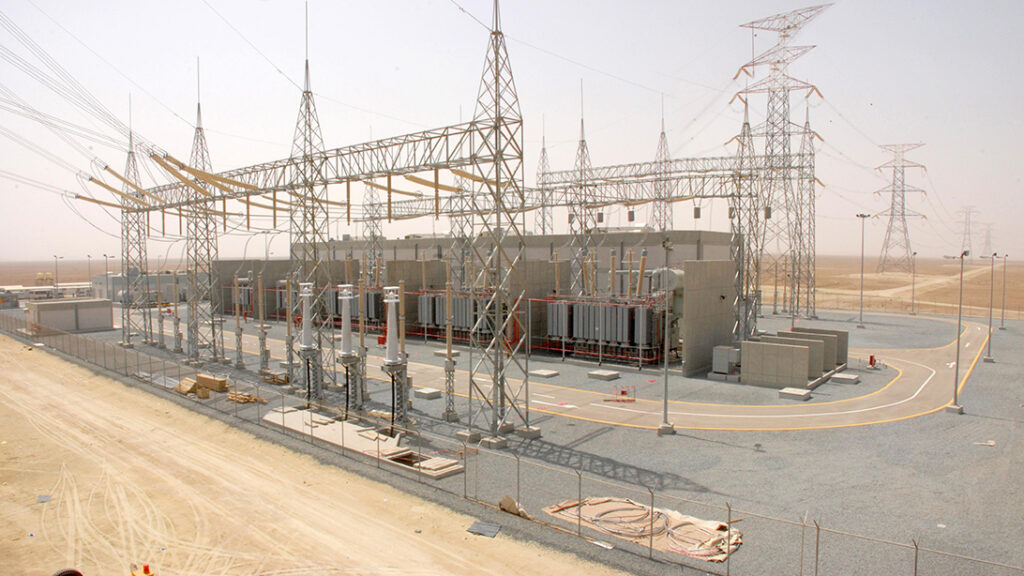
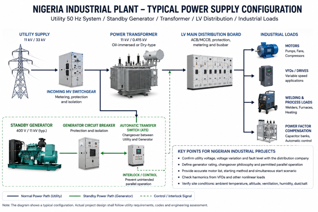
A factory transformer sits between a grid that may experience voltage variation and a production line that may contain motors, drives, welders, compressors, furnaces or refrigeration equipment. If the transformer is selected only from the sum of installed kilowatts, the result may be excessive voltage drop, nuisance tripping, overheating or unnecessary capital cost. Procurement should begin with the electrical chain: utility point of connection → incoming switchgear → transformer → LV or MV bus → motor control and process loads → standby generation → protection and metering.
Why Nigerian Industrial Transformer Selection Needs a System Review
Nigeria uses a nominal 50 Hz power system. Transmission Company of Nigeria has publicly referred to the Nigerian Grid Code frequency standard as 49.75–50.25 Hz. That system fact matters, but it does not replace a site-specific supply study. The serving distribution company, approved connection voltage, available fault level, feeder length and permitted protection arrangement should be confirmed for each project.
Two factories in the same state can face different electrical conditions. One may be supplied from a dedicated feeder with stable voltage. Another may share a long feeder with surrounding loads and operate standby generators for significant periods. Coastal sites around Lagos and the Niger Delta may place more emphasis on humidity, salt-laden air and corrosion, while inland sites may be dominated by dust, high ambient temperature or limited maintenance access. The transformer specification should reflect the actual location and operating pattern rather than a country label.
| Project condition | Impact on transformer | Main procurement risk | Recommended check |
|---|---|---|---|
| Utility voltage variation | Changes secondary voltage and flux conditions | Low process voltage or over-fluxing at an unsuitable tap | Obtain point-of-connection data and define tap range and tap operation |
| Standby generators | Changes source impedance, fault current and voltage regulation | Transformer inrush or motor starting destabilizes the generator bus | Review generator data, changeover philosophy and permitted parallel operation |
| Large motors and compressors | Creates starting current and short-duration voltage drop | Contactor dropout, relay operation or failed motor acceleration | Submit motor list, starting method and simultaneous-start scenario |
| Variable-frequency drives | Adds harmonic current and changes loss distribution | Unexpected winding heating and neutral or cable stress | Provide harmonic spectrum and confirm thermal evaluation |
| High ambient or restricted ventilation | Reduces available thermal margin | Continuous derating or high oil and winding temperatures | State site maxima, room ventilation and enclosure arrangement |
| Limited maintenance capability | Affects technology and accessory choice | Complex equipment remains out of service after a minor accessory failure | Agree spares, local indications, manuals and maintainable component brands |
Build the Capacity Calculation from the Load Schedule
Installed load is not the same as operating demand. A plant may have 4 MW of connected equipment but never operate every machine at full load. Another plant may have only 2 MW connected, yet run continuously near maximum demand with a poor power factor and repeated motor starts. The transformer kVA should be derived from active power, power factor, diversity, operating sequence and planned expansion.
Separate continuous, cyclic and starting duties
Continuous process loads set the basic thermal duty. Cyclic loads determine how often the transformer heats and recovers. Motor starting creates a short electrical and mechanical event that may be acceptable thermally but unacceptable for voltage stability. Procurement teams should not hide all three behind one “maximum demand” number.
When we review a motor-heavy plant, we normally ask for rated kW, efficiency, power factor, starting method, locked-rotor current where available, acceleration time and the simultaneous operating loads.
A larger transformer can reduce secondary voltage drop, yet oversizing increases capital cost and may reduce operating efficiency at light load. Lower impedance improves regulation but raises prospective fault current. The correct selection is a coordination exercise between source, transformer, switchgear, cables, protection and motor-starting requirements.
Keep expansion margin visible
Growth allowance should not be buried inside an unexplained diversity factor. State the present maximum demand, confirmed expansion, uncertain future load and required reserve separately. This makes technical and commercial comparisons much clearer. It also prevents a vendor from offering the same nominal capacity with a different interpretation of load margin.
For a practical reference on continuous manufacturing loads, review the 10 kV industrial park transformer application. Buyers evaluating a smaller distribution point can also compare the features of a 300 kVA oil-immersed transformer, while keeping in mind that project voltage, losses and accessories must be confirmed rather than copied from a standard product page.
Coordinate the Transformer with Utility and Generator Sources
Do not assume the same tap solves every voltage problem
An off-circuit tap changer is useful for setting the ratio when the normal incoming voltage is consistently above or below nominal. It is not designed to chase frequent voltage variation while energized. An on-load tap changer may be justified for certain duties, but it adds cost, controls, maintenance and protection interfaces. Many industrial distribution transformers are better served by a clearly chosen off-circuit tap range, proper feeder design and operational voltage monitoring.
Before specifying the tap arrangement, obtain the expected normal, minimum and maximum incoming voltage from the connection study or serving utility. Confirm whether generator operation uses the same transformer path. If the generator supplies the LV bus directly, the transformer may be isolated. If the generator back-feeds through a transformer for a permitted application, vector group, neutral grounding, protection directionality and operating interlocks require a dedicated study.
Generator capability can be the limiting source
Transformer energization produces inrush current. A stiff utility source may tolerate it, while a generator can experience a deep voltage dip or protection operation. The same applies when a large motor starts on a generator-backed bus. The generator transient reactance, excitation system, step-load capability and protection settings must be coordinated with the transformer and motor sequence.
In most industrial schemes we review, utility and generator sources are interlocked against unintended parallel operation unless synchronization and protection have been deliberately designed for it. The operating philosophy also needs to show how the plant moves from normal utility supply to generator operation, including generator start, bus transfer, load shedding and restoration.
Motor Loads, Drives and Harmonics Need Different Checks
A motor-starting study focuses on voltage drop and acceleration. A harmonic study focuses on current spectrum, losses, heating, resonance and power quality. They are related but not the same. When a plant has many variable-frequency drives, rectifiers, UPS systems or welders, the transformer supplier needs more than a statement that “harmonic loads are present.”
Provide the expected total harmonic current distortion and individual significant harmonic components at the transformer terminals. The engineer can then evaluate winding eddy loss, stray loss, neutral current where relevant and thermal margin. A transformer designed for a sinusoidal load should not automatically be assumed suitable for a heavily distorted current waveform at full nameplate load.
Power-factor correction capacitors also need system coordination. Installing capacitors without checking the harmonic environment can create resonance or overload capacitors. The transformer quotation should identify which harmonic assumptions are included and which system components remain outside the manufacturer’s scope.
| Input required | Why it matters | What should appear in the technical offer |
|---|---|---|
| Utility voltage and fault level | Sets ratio, insulation and protection basis | Rated voltages, highest voltage for equipment, impedance and fault-duty assumptions |
| Generator datasheet | Determines energization and transient performance | Interface assumptions and any operating restriction |
| Motor list and starting sequence | Determines voltage-drop scenario | Confirmed impedance and capacity basis |
| Harmonic spectrum | Changes conductor and stray-loss heating | Loss evaluation, conductor arrangement and any derating |
| Site ambient and installation | Defines cooling and enclosure duty | Cooling method, temperature-rise guarantee and enclosure/IP details |
| Maintenance resources | Influences accessories and spare strategy | Recommended spares, manuals and replaceable accessory list |
Choose Oil-Immersed or Dry-Type from the Installation Risk
Outdoor main distribution and heavy continuous loads often favour oil-immersed transformers because of their cooling performance and broad capacity range. Indoor installations with strict fire or oil-containment constraints may favour cast-resin dry-type units. Neither technology is universally superior.
An oil-immersed transformer requires attention to oil containment, fire separation, access and maintenance. A dry-type transformer requires adequate clean cooling air and protection from conductive dust, moisture and excessive ambient temperature. An enclosure can improve environmental protection but also restrict airflow, so its thermal effect must be considered.
For indoor production buildings, compare the site constraints with the available dry-type transformer range. For a packaged receiving and distribution arrangement, review the substation transformer and compact substation options. The selection should follow the fire strategy, room layout, feeder arrangement and maintenance plan.
Specify Site Conditions Without Using Vague Regional Labels
“Suitable for Africa” is not an engineering requirement. Nigeria includes coastal, humid and industrial environments as well as hotter, dustier inland locations. What we need instead is a defined site condition: maximum and minimum ambient temperature, altitude, humidity or condensation risk, pollution level, solar exposure, indoor or outdoor installation, corrosion category where applicable, and the available installation clearances.
Coastal or chemically aggressive sites may require a reviewed coating system, stainless or protected external hardware, suitable cable glands and attention to terminal boxes. Dusty sites need radiator cleaning access and protected control equipment. Indoor transformer rooms need a heat-rejection calculation based on transformer losses and room ventilation.
For a regional example of coastal industrial power design, the food-processing plant transformer project in Ghana illustrates how continuous production and local environment enter the discussion. A separate Nigeria-focused reference is our page on oil-immersed transformers for Nigerian distribution networks; its utility context should not be copied directly into an industrial plant without a new load review.
FAT and Documentation Should Support Commissioning
We prefer to close the FAT scope at purchase-order stage, not when the transformer is already approaching final assembly. Routine tests, any specified type or special tests, accessory functional checks and witness points all affect production planning. Reports should be traceable to the unit serial number and approved nameplate data. A generic certificate does not help the site engineer diagnose an abnormal reading.
For industrial projects, include ratio and vector-group checks, winding resistance, impedance and load loss, no-load loss and current, dielectric tests required by the applicable standard, oil tests where relevant, leak or pressure checks, and functional operation of fans, alarms, trips and indicators. The exact test list depends on transformer type, voltage class, contract and applicable standard.
Commissioning documents should state shipping condition, storage requirements, assembly steps, oil handling where applicable, pre-energization tests, torque values, alarm/trip settings and first-load monitoring. FAT values are most useful when the commissioning team can treat them as a baseline after installation. Oil condition, winding resistance, alarm settings and other recorded values can then be compared against the factory records when an abnormal reading appears on site.
Send the Data That Allows a Reliable Offer
For a Nigeria industrial transformer enquiry, send the single-line diagram, load schedule, motor list, generator datasheet, utility connection information, harmonic data, site conditions, installation layout and project specification. If some items are not yet available, identify them as open interfaces instead of replacing them with assumptions.
Zisheng Electric can supply oil-immersed distribution and power transformers, dry-type transformers, compact substations and related distribution equipment for industrial facilities. Our engineering team will review the requirements and respond to project inquiries within 24 hours. The first response will identify the confirmed selection basis, the missing project inputs and the technical points that need closure before manufacture.
About ZISHENG ELECTRICAL
Zisheng are a professional 19+ years manufacturer in producing Oil-Immersed Transformers, Compact Substation, Pad Mounted Transformers, Pole Mounted Transformers and Dry Type Transformers. We own the certificates of ISO/CE/IEC 60076 and TUV Rheinland.
Transformers undergo rigorous FAT and type testing, support voltage/capacity customization. Welcome to consult for Catalog and Product. you can contact us at email [email protected].