Transformer Protection Coordination for African Industrial Projects
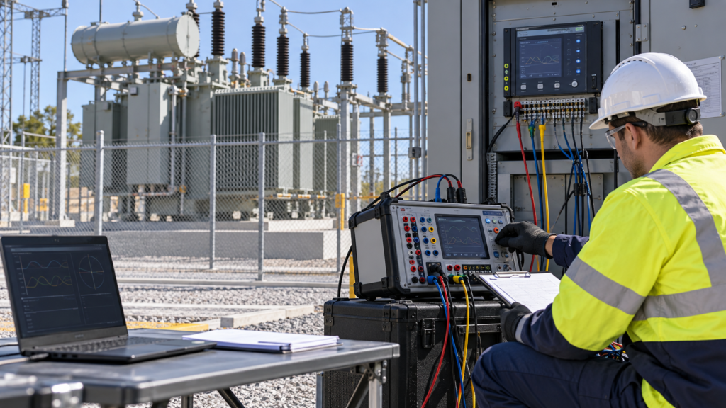
Transformer protection coordination should be reviewed as part of the complete power system rather than as an isolated relay setting. At Zisheng Electric, we evaluate how the transformer works with the utility feeder, medium-voltage switchgear, generator or solar source, large motors and the site earthing system.
Why transformer protection coordination matters
A protection scheme must clear faults quickly while remaining stable during energisation, motor starting and upstream disturbances. If CT ratio, relay curve or trip logic is selected without the complete network, nuisance trips and delayed fault clearing can both occur.
Industrial sites often combine utility supply with standby generation, long cable runs, process motors and changing production loads. Use the actual utility short-circuit level, transformer impedance, neutral arrangement, cable data and motor contribution instead of a generic relay template.
Transformer protection coordination checks
| Design factor | Main risk | Engineering check |
|---|---|---|
| CT ratio and class | Saturation during through-faults | Check rated current, fault duty, burden, knee point and wiring length. |
| Magnetising inrush | Energisation mistaken for an internal fault | Use inrush restraint or blocking logic and verify it in a switching study. |
| Neutral grounding | Earth-fault sensitivity is lost or excessive | Confirm vector group, grounding method and CT location. |
| Downstream selectivity | A feeder trip disconnects the whole plant | Coordinate curves with LV/MV feeders and motor protection. |
| Trip circuit supervision | Failed trip path remains hidden | Test DC alarms, breaker failure and lockout logic. |
CT selection and differential protection
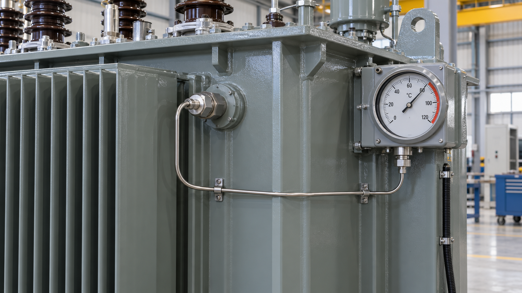
Protection CTs should be selected from maximum continuous load, prospective fault current and relay burden. A ratio that is too low may saturate during an external fault. A ratio that is too high reduces sensitivity to low-level earth faults. Reusing an existing switchgear panel without checking CT class and secondary wiring creates avoidable risk.
Differential protection
For medium and large transformers, differential protection compares currents on both sides after ratio and phase compensation. The relay must understand the vector group and zero-sequence treatment. CT polarity must be verified at the panel and transformer terminals. During FAT, the manufacturer and EPC contractor should agree how injection results are recorded.
Overcurrent and earth-fault protection
Overcurrent elements provide backup for feeder, cable and transformer faults. Pickup should sit above expected load and starting current while remaining below the minimum fault current that must be cleared. Earth-fault settings depend on the grounding method; solid grounding and a neutral grounding resistor require different sensitivity and delay.
Managing inrush and motor starting
Transformer energisation can produce a high transient current that decays over several cycles. The relay scheme should distinguish this event from an internal winding fault. Record harmonic restraint logic and blocking time in the protection philosophy. Large motors create a different problem: starting current can depress voltage and cause an upstream element to operate if time grading is too narrow.
For plants with frequent motor starts, identify motor size, starting method, acceleration time and restart sequence. Transformer impedance and tap position must be considered with the motor protection curve. A protection study that ignores the motor list is incomplete.
Grounding and EPC interface details
The single-line diagram should show transformer neutral treatment, earthing transformer connections, CT locations, surge arresters, cable screens and the trip path to the MV breaker. These details affect relay measurements and maintenance safety. They also determine what must be tested at site.
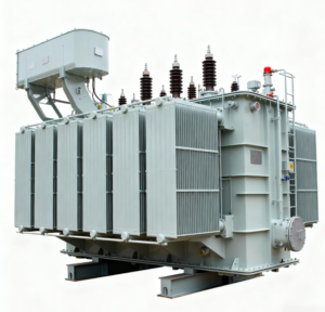
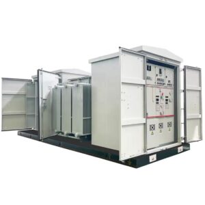
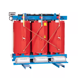
For African industrial projects, long delivery routes, high ambient temperatures, dust and limited local spare capacity should be reflected in the procurement package. Specify terminal markings, spare contacts, protection wiring, test plugs, relay files and recommended spares. Zisheng Electric can coordinate these interfaces for oil-immersed transformers, dry-type transformers and compact substations.
FAT and commissioning evidence

A useful FAT is more than a relay screen print. Test CT polarity, ratio, secondary injection, differential restraint, overcurrent timing, earth-fault pickup, breaker trip, lockout, alarm contacts, DC failure and communication mapping. The final file should include approved settings, test values, wiring references and punch-list closure.
Review transformer transport inspection and neutral grounding resistor interfaces with the protection study.
Data package for review
Before quotation, send the transformer datasheet, single-line diagram, utility fault level, load schedule, motor list, cable schedule, grounding philosophy, relay make and model, CT data and environmental conditions. If the utility has a project-specific protection standard, include the latest approved version.
Send Zisheng Electric your drawings, datasheets, load list, technical specification, single-line diagram, grid parameters and site conditions. Our engineering team will review the requirements and respond to project inquiries within 24 hours.
About ZISHENG ELECTRICAL
Zisheng are a professional 19+ years manufacturer in producing Oil-Immersed Transformers, Compact Substation, Pad Mounted Transformers, Pole Mounted Transformers and Dry Type Transformers. We own the certificates of ISO/CE/IEC 60076 and TUV Rheinland.
Transformers undergo rigorous FAT and type testing, support voltage/capacity customization. Welcome to consult for Catalog and Product. you can contact us at email [email protected].