Transformer Bus Duct Interface for Middle East Industrial Plants: Flange, Expansion and Thermal Duty
Zisheng Electric reviews a transformer bus duct interface as a physical and electrical boundary, not merely as a matching current rating on two equipment schedules. An industrial plant may order a transformer, low-voltage switchgear and enclosed busbar trunking from separate suppliers. Each component can pass its own factory inspection while their connection still arrives with mismatched flange dimensions, inaccessible bolted joints or no agreed support for thermal movement. The cost appears late, when the building is closed and the energization date is close.
This guide is for EPC buyers and plant engineers planning an industrial distribution package in the Middle East. The regional label does not establish a design temperature, grid frequency, corrosion category or utility approval. Record the actual project site conditions and the receiving utility’s written requirements before fixing equipment ratings. The useful procurement question is whether the transformer terminal, bus duct, building route and receiving switchboard form a connection that can be built, tested and maintained together.
Define the transformer bus duct interface before release
Start with a one-line diagram that identifies the transformer winding, nominal system voltage, connection point, short-circuit study case and downstream board. Then bring the general-arrangement drawings together at the same revision. The transformer supplier needs the bus duct terminal arrangement, and the bus duct supplier needs the transformer terminal geometry and allowable connection loads. The civil contractor needs the route, penetrations and independent support points. A purchase order that says only “bus duct by others” leaves these interfaces unresolved.
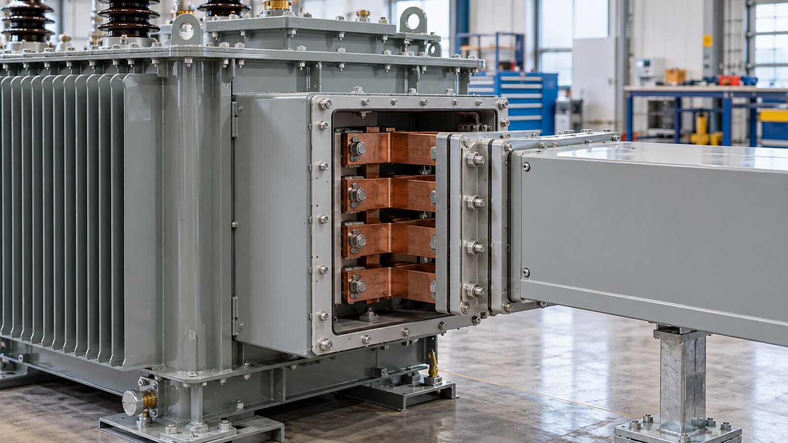
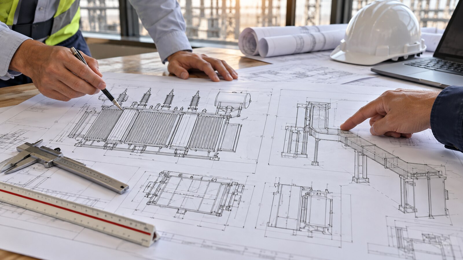
Assign one party to issue the integrated connection drawing. This should show the transformer terminal enclosure, removable cover, flange plane, phase order, neutral arrangement where applicable, earthing bond, bus duct direction, expansion allowance, support locations and maintenance clearances. Record the drawing revision accepted by each supplier. If the transformer is changed after the bus duct fabrication drawing is approved, reopen the interface review rather than assuming the dimensional difference is harmless.
Agree who supplies each piece
The boundary can sit at the transformer terminal pads, a connection box flange or a short transition section. Each arrangement changes responsibility for flexible connections, insulating barriers, terminal hardware, enclosure continuity and on-site assembly. A single scope matrix should name the party furnishing, installing and testing each item. Distinguish mechanical supply from electrical test ownership; an installer may fit a component supplied by another vendor, but the test procedure still needs a named signatory.
Translate load data into connection duty
The transformer nameplate current is a starting point, but the connection also sees the plant’s operating pattern, possible future stages and fault conditions. Obtain the load list and the demand profile. Identify large motors, drives, power-factor equipment and standby sources. A future production line may change expected continuous loading without changing the first construction phase. If the buyer requests a different transformer rating, recheck the bus duct and receiving switchboard rather than changing only the transformer schedule.
For a busbar trunking system, the procurement specification should identify the applicable product standard and the agreed edition. IEC lists IEC 61439-6 as the part dealing with busbar trunking systems. Citing the title is not a substitute for obtaining the manufacturer’s verified assembly data or confirming that the selected system meets the project’s contract. Ask for the declared current rating under the installation conditions, short-circuit ratings and the type of connection unit actually offered.
Elevated ambient temperature can affect enclosure heat rejection and current capability. Sun exposure, indoor ventilation, proximity to hot process equipment, dust and local corrosion all depend on the specific site and route. Ask the bus duct manufacturer to declare any rating adjustment for the approved installation. Avoid importing a generic “Middle East temperature” into the order; the owner should supply the governing design ambient and required temperature-rise basis.
| Interface decision | Project evidence to request | Why it affects procurement |
|---|---|---|
| Continuous current and growth | Load list, demand profile, future phase and transformer rating | Prevents a connection sized only for the first operating case. |
| Fault duty | Approved short-circuit study and equipment withstand declarations | Aligns bus duct, joints and switchboard with the same study case. |
| Terminal geometry | Coordinated GA, flange drawing, phase sequence and tolerance | Prevents site drilling or improvised transition pieces. |
| Thermal movement | Route length, support design and expansion detail | Limits unintended mechanical force at transformer terminals. |
| Earthing and neutral | Single-line, bonding detail and neutral scheme | Keeps protective and return-current paths explicit. |
| Access and testing | Joint locations, removable covers, test plan and as-built route | Allows inspection and fault investigation after installation. |
Separate support loads from terminal loads
A long or heavy bus duct route must not use the transformer bushings or terminal box as an unintended structural anchor. The mechanical design should give the route its own supports, including any necessary flexibility at the transformer connection. Ask each supplier to state allowable static and dynamic loads at the interface. The approved layout must account for construction tolerances, seismic or vibration design where the project requires it, and movement from operating temperature changes.
A short rigid connection may look clean on a drawing but transfer building movement or support settlement into the transformer enclosure. Conversely, an unrestrained flexible piece may compromise clearance or enclosure integrity. The selected arrangement should be explained by the designers of both systems and checked against the real support spacing. Note which joints can be removed without moving the transformer or dismantling a long run of bus duct.
Where the route passes a wall or fire compartment, coordinate the opening size, firestop and inspection access with the civil and fire disciplines. Do not assume the electrical supplier’s enclosure automatically completes the building penetration. Record who seals the annular space and who will provide the as-built evidence. The auxiliary power specification guide offers a parallel example of why supplier boundaries should be frozen before panel drawings and site routes are released.
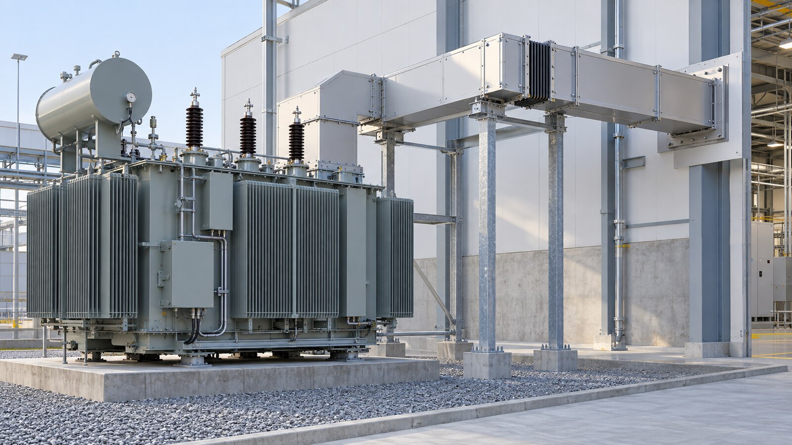
Check phase sequence, neutral and enclosure continuity
Mark the phase order at both equipment ends on the same drawing and confirm the viewpoint. A drawing can appear consistent until one supplier looks toward the transformer and the other looks toward the switchboard. Include terminal identification and orientation in the approved interface package. On site, verify before making a joint; the installation team should not infer phase order from enclosure shape or color alone.
If the system has a neutral conductor, document its size, path, termination and operating duty. The neutral arrangement follows the approved single-line and load characteristics, including any unbalanced or nonlinear loads. Ask for the design basis if harmonics are significant. Do not treat the enclosure as a substitute for a specified neutral or protective conductor. The protective bonding path across the transformer enclosure, flexible element, bus duct and switchboard should be drawn and tested as the project procedure requires.
In parallel, coordinate CT and metering locations. An instrument transformer near one side of the connection can include or exclude auxiliary or process loads differently from one on the other side. The transformer metering interface guide explains how an agreed measurement boundary supports procurement and acceptance. Apply the same boundary discipline here, even though the plant location and operating contract differ.
Plan enclosure, ingress and maintenance access
A connection enclosure has to protect personnel and components in the installed environment. Specify the required ingress protection and material finish from the project conditions rather than from a country label. Dust, cleaning methods, indoor humidity, coastal exposure and nearby process emissions vary greatly between sites. Compare the offered terminal box and bus duct enclosures at their joint; the interface should not become the weakest point because two independently rated housings are connected by an unreviewed adaptor.
Access is also an operating requirement. Can a technician safely isolate and inspect the connection? Are bolted joints and temperature measurement points reachable without removing structural steel? Is there room to open covers after cable trays, sprinklers and ventilation ducts are installed? Sketch the maintenance envelope on the layout and have the construction team check it against other trades. Provide a safe inspection sequence and the relevant isolation boundaries in the handover documents.
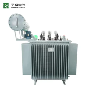
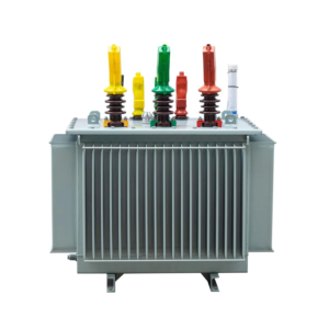
A product decision can start with a 400kVA oil-immersed distribution transformer configured with a project-approved low-voltage secondary. The receiving custom low-voltage switchgear must have a matching rated voltage and be reviewed with the same route, short-circuit and access data. These linked products are equipment examples, not a claim that a particular pair or bus duct connection is preapproved.
Build inspection and test evidence into the purchase order
Factory inspections should cover what can be verified before shipment: terminal geometry, enclosure and flange dimensions, phase identification, available clearances, supplied transition components and the agreed connection drawing. A transformer FAT alone cannot demonstrate the performance of an assembled bus duct route that does not yet exist. Likewise, a bus duct factory record does not prove that the final site support positions, alignment and bonding have been achieved.
At receipt, check for transit damage and verify the shipped parts against the packing list and drawing revision. Before energization, record support installation, joint surfaces, specified fastener method, phase continuity, protective bonding, insulation checks and any approved site tests. Test limits and methods must come from the equipment manufacturers and project procedure. Keep results traceable to joint and segment identifiers; a single pass/fail note for the whole route is weak evidence when an individual joint later needs investigation.
Do not use temperature imaging immediately after first energization as a substitute for proper assembly records. A thermal survey can be valuable under a documented load and environmental condition, but its interpretation depends on current, accessibility, emissivity and comparison points. If the project requires a first-service survey, agree who performs it, when useful load is available and how abnormal readings are dispositioned.
Control changes during construction and handover
Routing changes are common when structural steel, cable trays or process pipework compete for space. Each change should be assessed for support loading, thermal expansion, enclosure rating and maintenance access before installation. Issue a revised interface drawing and update the procurement deviation register if a component changes. An installer should not improvise a transition by cutting the enclosure or drilling terminal pads without a written engineering disposition.
The final dossier should contain the approved one-line diagram, transformer and switchgear data sheets, coordinated GA drawings, bus duct manufacturer data, interface scope matrix, installation records, inspection and test results, deviations, as-built route and maintenance instructions. If utility approval is part of the project, record the actual utility’s written interface conditions; do not assume a general national rule covers the plant arrangement. The load shedding and restoration interface article provides a related reminder that electrical boundaries must remain clear through commissioning and operation.
What to send for a transformer bus duct interface review
Zisheng Electric can review a transformer bus duct interface alongside the relevant power transformer and low-voltage switchgear scope. Send the drawings, equipment data sheets, load list, technical specification, single-line diagram, grid parameters, environmental conditions and installation-site conditions. Add the proposed bus duct route, support scheme, connection drawing, short-circuit study and any utility or owner interface requirements. We can then identify open dimensions, ownership gaps and the evidence needed before procurement release. Our engineering team will review the requirements and respond to project inquiries within 24 hours.
About ZISHENG ELECTRICAL
Zisheng are a professional 19+ years manufacturer in producing Oil-Immersed Transformers, Compact Substation, Pad Mounted Transformers, Pole Mounted Transformers and Dry Type Transformers. We own the certificates of ISO/CE/IEC 60076 and TUV Rheinland.
Transformers undergo rigorous FAT and type testing, support voltage/capacity customization. Welcome to consult for Catalog and Product. you can contact us at email [email protected].