Transformer Failures: Causes, Analysis & Practical Prevention Tips

Why Do Transformer Failures Occur? An Analysis of Key Issues in Selection, Operation, and Maintenance Based on Field Case Studies

Why Do Transformer Failures Occur? An Analysis of Key Issues in Selection, Operation, and Maintenance Based on Field Case Studies

Transformer failures are a frequent headache for power distribution projects, especially in harsh operating environments across Africa and the Middle East. Many site operators face unexpected shutdowns, costly repair work and long power outages due to avoidable transformer faults. Based on our on‑site service experience, this article breaks down the main root causes behind transformer failures and offers actionable technical guidance for field engineers and project buyers.

transformer failures inspection with thermal imaging for distribution power transformer

Over the past few years, while participating in on-site services for industrial, renewable energy, and power distribution projects, Zisheng Electric engineers have observed a recurring phenomenon: the issues that truly cause unplanned downtime are often not sudden equipment failures. Instead, they usually start from small problems that seem insignificant during commissioning — issues that are overlooked during installation, gradually worsen after three to five years of operation, and eventually develop into failures. The overall losses can far exceed the cost of a new transformer.

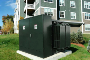
Saudi Arabia Commercial Complex, 1250kVA Dry-Type Transformer

The transformer operated normally for the first two years. Starting from the third summer, frequent temperature control alarms began to occur.

All factory test parameters were qualified, but the installation location was in an underground equipment room. The building’s air-conditioning system mainly served commercial areas and did not provide dedicated ventilation for the transformer room.

When outdoor temperatures reached 45℃ in summer, heat continuously accumulated inside the equipment room, causing the transformer to operate near its temperature rise margin for extended periods.

Northern Chile 50MW Solar PV Project, 35kV Compact Transformer

After approximately one and a half years of operation, the site maintenance team discovered during quarterly oil sample testing that the acetylene content in the transformer oil of one unit showed a continuous increasing trend.

The initial data had not yet reached the alarm threshold, but after reviewing historical trends, we determined that this change could not simply be considered random fluctuation.

The transformer passed all factory tests, and protection devices had never operated.

The Atacama Desert in Chile experiences extreme temperature differences between day and night. Each day, the photovoltaic system goes through a cycle of:

Morning rapid load increase → Noon full power generation → Evening sudden reduction to no load.

The accumulated mechanical and thermal stresses caused winding support blocks to loosen, minor coil displacement, and reduced tightening force at leads and connections.

After component micro-movement, friction, and poor contact occurred, localized arc discharge was triggered, generating acetylene.

South Africa Industrial Processing Plant

The transformer capacity was initially designed based on the original load demand. Two years later, new production lines were added, causing the load rate to remain above 90% for extended periods.

Due to the long expansion cycle of the local power grid, the company had no choice but to continue operating under high load conditions.

By the fifth year, the transformer’s insulation performance had significantly deteriorated, eventually requiring shutdown and maintenance.

Site personnel often ask:

“Is there a problem with the transformer quality?”

However, from an engineering perspective, most failures cannot simply be attributed to the manufacturing side.

Many problems occur before the equipment is even energized — due to insufficient design inputs, inadequate evaluation of installation conditions, and missing or ineffective operation management later in the equipment lifecycle.

A transformer expected to operate reliably for more than 20 years in real-world conditions is not running in a temperature-controlled laboratory. It must withstand:

  • Outdoor temperatures exceeding 45℃ in summer;
  • Dust accumulation and poor ventilation in substations;
  • Grid voltage fluctuations and lightning surge impacts;
  • High loading rates running continuously day and night;
  • Frequent changes of maintenance personnel;
  • Loss of operation records.

The reliability of a transformer is not determined only by its factory test report. The real question is whether it can withstand the “invisible stresses” it faces on site.

Below, based on our accumulated field experience from industrial, renewable energy, and commercial building projects, we will analyze several common transformer failures — from their failure mechanisms, early detection methods, to fundamental prevention measures — and explain them as practically as possible.

1. Abnormal Temperature Rise: The Most Common “Chronic Disease” — Usually Not a Manufacturing Quality Issue

2 transformer field inspection engineer infrared camera

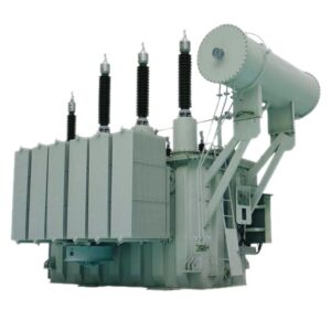
1.1Case: Saudi Arabia Industrial Project — 2500kVA Oil-Immersed Transformer

The project installed one 2500kVA oil-immersed transformer. The designed capacity met the initial production requirements, losses complied with IEC 60076, and all factory tests were successfully passed.

Six months after commissioning, the owner reported frequent temperature alarms during the high-temperature period every afternoon.

Site inspection findings:

  • Actual load verification: during the afternoon production peak, the load rate reached approximately 95%;
  • Installation environment inspection: installed on an outdoor platform, with summer maximum temperatures exceeding 45℃. The transformer was exposed to direct sunlight, surrounding dust accumulation was significant, and visible dust buildup was found on the surface of the radiators;
  • Operating data review: the transformer operated under high load continuously for several hours every day.

Conclusion:
This was not a manufacturing defect. The high ambient temperature + reduced heat dissipation caused by dust accumulation + long-duration high-load operation together resulted in abnormal temperature rise.

1.2Why Does a Transformer Overheat Even When the Capacity Is “Sufficient”?

This is a common selection mistake.

The rated capacity on the nameplate does not mean the transformer can always operate at full load under any environmental condition.

A 1000kVA transformer represents the rated capacity under standard reference conditions:

  • Maximum ambient temperature: 40℃;
  • Altitude: ≤1000m;
  • Harmonic conditions within standard limits.

A rough estimation:

Standard transformer design usually considers a 40℃ ambient temperature. If the actual environment reaches 45℃, the temperature rise margin is immediately reduced by 5K.

If the transformer operates at 100% load continuously, the winding temperature rise may exceed the design value by 8–10K.

When these two factors are combined, the actual operating temperature may exceed the design limit by more than 10℃.

Higher temperature is not just an alarm issue — it directly causes service life reduction.

The thermal aging of oil-immersed transformer insulation follows the “10-degree rule”:

Every 10℃ increase in operating temperature approximately reduces insulation life by half.

A transformer designed for a 20-year service life may approach the end of its insulation life within only 8–10 years if it operates above temperature limits for long periods.

1.3From an Engineer’s Perspective, Practical Solutions to Overheating

(1) Capacity Design Should Not Only Consider Current Load

For commercial buildings, industrial plants, and data centers, it is recommended to reserve 15%–20% capacity margin based on calculated load.

If the owner has a clear expansion plan, select transformer capacity according to the future expanded load directly.

(2) Quantitatively Evaluate Heat Dissipation Conditions Instead of Simply Saying “Good Ventilation”

Outdoor installation without obstruction:

  • Provides the best natural ventilation;
  • However, solar radiation and rain protection must also be considered.

Indoor substation room:

  • Calculate room volume;
  • Verify louver area;
  • Confirm exhaust fan airflow capacity.

Basement or mezzanine installation:

  • Must be equipped with independent mechanical ventilation;
  • Do not share ventilation systems with smoke extraction or building air-conditioning systems.

(3)Critical Projects Should Use Fiber-Optic Winding Temperature Monitoring

Do not rely only on top oil temperature measurement.

The winding hot spot temperature is the real “body temperature” of the transformer. It reflects the thermal condition inside the transformer more accurately than oil temperature.

In recent years, the cost of fiber-optic temperature monitoring has decreased significantly. For critical transformers above 2000kVA, this investment is worthwhile.

(4) Connect Temperature Monitoring Data to the Management System and Enable Trend Warnings

Many failures do not happen suddenly.

If the system can identify a continuous temperature increase before reaching the alarm threshold and provide a warning such as:

“Winding temperature has increased by 5℃ over the past week. Please check ventilation conditions.”

Many shutdown incidents can be prevented in advance.

2. Insulation Aging: The Silent “Life Killer” — Often Discovered Too Late

Abnormal temperature rise usually triggers an alarm light, but insulation aging is silent.

The transformer’s internal insulation system — including inter-turn insulation, layer insulation, main insulation, and lead insulation — continuously suffers from the combined effects of electrical stress, thermal stress, mechanical stress, and chemical stress. Its performance gradually declines over years of operation.

Once the insulation condition reaches a critical point, it may trigger a chain reaction:

Partial discharge → Inter-turn short circuit → Main insulation breakdown

2.1Case: Insulation Risk Caused by Thermal Cycling in a Chile PV Project

The project used multiple 33kV/0.8kV box-type step-up transformers, each rated at 2000kVA. The equipment had been operating for more than one year without any protection trips.

During routine dissolved gas analysis (DGA) testing, two transformers were found to have significantly elevated acetylene (C₂H₂) levels. Although the values had not yet reached the alarm threshold, the trend was abnormal.

Root Cause Investigation:

The root cause was related to the natural operating characteristics of photovoltaic plants:

Sunrise: rapid increase from zero load to full load
Midday: maximum power generation
Sunset: rapid reduction back to zero load

This creates one complete thermal cycle every day.

During high-temperature summer periods, daily winding temperature fluctuations could reach 40–50℃.

Long-term thermal cycling resulted in:

  • Different thermal expansion coefficients between copper conductors and insulation materials, causing small relative movements;
  • Gradual reduction of degree of polymerization (DP) of insulating paper, as high temperature accelerates cellulose degradation;
  • If the winding clamping force was insufficient, looseness could develop, causing partial discharge and accelerating insulation damage.

Key Lesson:

The daily load cycling of PV transformers and the continuous high-load operation of industrial transformers create completely different insulation damage mechanisms.

They cannot be evaluated using the same design assumptions.

2.2Common Field Manifestations of Insulation Aging

Aging Factor Common Site Symptoms Root Cause Consequences
Thermal aging Continuous increase of CO/CO₂ in oil; darker insulation paper color Long-term overheating (undersized selection / insufficient cooling) Reduced insulation strength and shortened service life
Moisture ingress Reduced oil breakdown voltage; moisture content >30ppm Breather failure / aging seals / moisture introduced during installation Significant reduction in breakdown voltage and accelerated paper insulation degradation
Partial discharge Ultrasonic detection signals; increasing C₂H₂ content in oil Winding looseness / sharp-point discharge / internal air gaps / floating potential Gradual erosion of insulation, developing into inter-turn or main insulation breakdown
Oil oxidation Darker oil color; increased acid value; reduced interfacial tension High temperature + oxygen exposure (poor oil conservator sealing) Overall oil performance degradation and accelerated insulation aging

2.3Combined Testing Methods for Early Insulation Problem Detection

(1)Dissolved Gas Analysis (DGA)

Recommended once every six months.

Key monitoring parameters:

  • C₂H₂ (acetylene)
  • CO
  • CO₂
  • Total hydrocarbons

A single abnormal result is important, but trend analysis is even more important.

For example, if the acetylene level of one transformer continues increasing for two consecutive quarters, it should be treated as a warning even if it is still below the official limit.

(2)Insulation Resistance and Dielectric Loss Testing

Recommended annually.

Used to evaluate:

  • Overall moisture condition;
  • Insulation aging condition.

During testing, record:

  • Ambient temperature;
  • Humidity;
  • Transformer winding temperature.

Insulation resistance changes significantly with temperature. Test data without temperature correction has limited comparison value.

(3)Partial Discharge Testing (Ultrasonic or High-Frequency Current Method)

Online monitoring without shutdown.

For critical projects, it is recommended to perform a baseline test six months after commissioning, followed by annual comparison.

(4)Establish a “One Transformer, One File” Operation Record

All information should be archived:

  • Factory test results;
  • Installation and commissioning records;
  • Routine inspection records;
  • Oil test results;
  • Load operation history.

Only with sufficient historical data can engineers accurately distinguish between:

“normal aging” and “abnormal risk.”

3. Main Reference Standards for Transformer Fault Evaluation

Actual engineering assessments usually consider:

  • IEC 60076 series (Power Transformers)
  • IEC 60599 (Dissolved Gas Analysis of Oil-Immersed Transformers)
  • IEEE C57 series (Operation and Maintenance Guidelines)

Different projects may have different technical requirements, but the core principle remains the same:

Identify risks in advance by analyzing trends in:

  • Temperature
  • Insulation condition
  • Oil quality
  • Electrical performance

4. Oil Leakage Fault: Small Problems Should Not Be Ignored

Oil-immersed transformer oil leakage is a common issue in outdoor projects.

Many site personnel consider minor oil seepage as “not serious” and choose to continue operation temporarily. However, from an engineering perspective, any oil leakage should be addressed immediately and should not be delayed.

Transformer oil has two critical functions:

  • Cooling medium
  • Insulation medium

Long-term oil leakage can cause:

  • Oil level reduction, exposing the upper winding to air and causing a sharp decrease in insulation strength;
  • External moisture entering through leakage points, increasing moisture content;
  • Reduced oil volume, weakening circulating cooling capability and worsening temperature rise.

4.1Most Common Oil Leakage Locations on Site

(1) Tank Cover and Tank Flange Sealing Area

Large-capacity transformer tank covers are large in size. Uneven bolt tightening or aging sealing gaskets can cause leakage.

(2)High-Voltage / Low-Voltage Bushing Base

Thermal expansion and contraction stresses concentrate in this area, causing sealing rings to age, crack, and lose effectiveness.

(3)Radiator and Tank Connection Flanges

Vibration and thermal cycling can loosen bolts and cause gasket failure.

(4)Drain Valve and Oil Sampling Valve

Common causes include aging sealing components or incomplete closing after operation.

4.2Case: Outdoor Transformer Oil Leakage in UAE

An oil-immersed transformer in an industrial project was inspected during its third year of operation. Minor oil seepage was found at the bottom of the tank.

Because the transformer was still operating normally, the team decided to postpone repair.

However, in the Middle East:

  • Daytime temperatures exceed 45℃;
  • Large temperature differences occur between day and night;
  • Severe dust exposure exists.

Continuous thermal cycling accelerated seal gasket aging, while dust accumulation around the leakage area further worsened the condition.

Six months later:

  • Oil level decreased;
  • Moisture content increased;
  • Insulation performance deteriorated;
  • The transformer eventually had to be shut down.

If the sealing component had been replaced at the initial stage, the repair would have taken only several hours.

At the later stage, the repair required:

  • Oil draining;
  • Drying treatment;
  • Re-testing.

The maintenance cost increased several times.

4.3Correct Oil Leakage Handling Process

Leakage detected

Record location and leakage amount (take photos and keep records)

Determine severity:

  • Minor seepage or obvious dripping?
  • Leakage frequency?

    Identify the cause:
  • Seal aging?
  • Loose bolts?
  • Welding cracks?

    Develop repair plan:
  • Minor leakage: tighten bolts under controlled conditions or replace sealing rings;
  • Severe leakage: power shutdown, oil draining, and repair required.

    Post-repair testing:
  • Sealing test
  • Oil breakdown voltage test

Confirm no abnormality before returning the transformer to operation.

5. Winding Failure: The “Hidden Fracture” Left by Short-Circuit Impact

The winding is the heart of the transformer.

During normal operation, it continuously withstands:

  • Thermal stress
  • Mechanical forces

When a grid short circuit occurs, the huge short-circuit current (which can reach 10–20 times rated current) generates extremely strong electromagnetic forces between windings.

This may cause:

  • Axial or radial winding deformation;
  • Compression damage to insulation layers;
  • Changes in turn-to-turn spacing;
  • Electric field distortion.

The most easily overlooked point is:

After a short-circuit impact, the transformer may still continue operating normally.

It is like a bone with a small crack — a person may still be able to walk, but the structure is no longer in perfect condition.

After repeated impacts or another load disturbance, the existing damage may continue developing and eventually lead to insulation failure. In severe cases, conductor breakage may occur.

5.1Case: Industrial Park Project in Russia

A 2000kVA oil-immersed transformer experienced a grid short circuit during its third winter of operation.

Protection devices operated, and the transformer was re-energized afterward.

Because power supply remained normal, no further inspection was carried out.

One year later, another failure occurred.

Factory inspection found:

  • Significant axial deformation of the low-voltage winding.

Analysis showed:

  • Large seasonal load variations in winter;
  • Frequent startup of large equipment;
  • Increased starting impact current;
  • Mechanical stress changes caused by low temperatures.

The previous short-circuit event had already caused minor deformation. Because it was not detected in time, the damage gradually developed into insulation failure.

5.2Preventing Winding Failures from the Source

(1)Specify Higher Short-Circuit Withstand Capability During Selection

Technical specifications should include requirements such as:

  • “Short-circuit impedance shall not be lower than the required standard value”;
  • “Windings shall use semi-hard copper conductors”;
  • “Additional end clamping structures shall be provided.”

Do not only state:

“Comply with IEC 60076.”

(2)Pay Attention to Short-Circuit Testing Before Delivery

For industrial projects or critical grid nodes, it is recommended to require:

Short-circuit withstand capability type test reports

(real physical tests, not only calculation reports).

(3) Control Short-Circuit Impact Frequency During Operation

If a system experiences a short-circuit trip:

It is recommended to perform:

Winding deformation analysis using Frequency Response Analysis (FRA)

to determine whether mechanical deformation has occurred.

Do not ignore the issue simply because:

“The transformer is still operating.”

6. New Challenges in the Renewable Energy Era: Load Cycling, Harmonics, and Harsh Outdoor Environments

5 solar farm transformer skid mounted box transformer

With the rapid growth of photovoltaic, wind power, and energy storage projects, transformer operating conditions have undergone profound changes. The traditional operating model of “stable operation throughout the year” has been fundamentally changed.

Application Scenario Operating Characteristics Main Risk Points Special Requirements for Transformers
Photovoltaic Power Plants Full load from sunrise and no load after sunset, creating a complete thermal cycle every day Thermal cycling causes winding loosening and insulation fatigue Strengthened clamping structure; insulation materials with Class H heat resistance
Wind Power Projects Output power fluctuates significantly with wind speed, with frequent power ramping Rapid load changes create thermal stress; nacelle vibration affects mechanical strength Stronger overload capability and anti-vibration design
Energy Storage Projects High-frequency charging and discharging with large current variation rates Frequent current impacts and thermal cycling Reduced winding current density, strengthened mechanical structure; use of low-loss silicon steel sheets
Offshore Wind Power High humidity, salt spray corrosion, and difficult maintenance conditions Corrosion failure, sealing damage, and condensation Anti-corrosion level ≥ C5-M; IP56 protection as minimum requirement; fully sealed structure
Commercial & Industrial Energy Storage Daily charging during the day and discharging at night, intermittent operation Moisture absorption risk after long shutdown periods Automatic anti-condensation heaters; increased inspection frequency

Key Recommendations for Renewable Energy Project Owners

Do not directly apply traditional grid distribution transformer selection experience to renewable energy projects.

Different operating modes determine completely different failure mechanisms.

It is recommended that technical specifications clearly state:

“This equipment is intended for photovoltaic / wind power / energy storage applications and shall be specially designed to withstand daily load cycles, load fluctuations, and high-frequency charging and discharging conditions.”

Only by incorporating these requirements into the contract can the supplier be ensured to perform targeted design for special operating conditions, instead of simply offering standard products for bidding.

7. Transformer Maintenance: Moving from “Repair After Failure” to “Predictive Maintenance”

In the past, many companies followed this maintenance model:

Normal operation → No attention → Fault alarm → Shutdown maintenance → Recovery

This reactive maintenance approach may have been acceptable 20 years ago.

However, today:

  • A one-minute power interruption in a semiconductor factory can cause millions in losses;
  • Data center outages can result in immeasurable data losses;
  • Commercial complex blackouts can lead to customer complaints, compensation claims, and reputation damage.

Therefore, more and more projects are adopting predictive maintenance.

The core concept is:

Before failures occur, identify risks in advance through continuous monitoring and data analysis, then take preventive actions.

The key point is:

Monitoring itself is not the goal.

Establishing a “health baseline” and tracking “change trends” is what truly matters.

For example:

A transformer’s C₂H₂ (acetylene) level is:

  • 0.1ppm at commissioning;
  • 0.8ppm after one year.

Although 0.8ppm is still far below the alarm threshold (usually around 5ppm), the concentration has increased by seven times.

This is an important risk signal.

Without baseline data, engineers may ignore the value because:

“0.8ppm is still within the limit.”

With:

  • Baseline data;
  • Comparison analysis;
  • Trend monitoring;

true early risk prediction becomes possible.

8. Design and Manufacturing Control from an Engineering Perspective

6 power transformer factory acceptance test IEC 60076

About ZISHENG ELECTRICAL

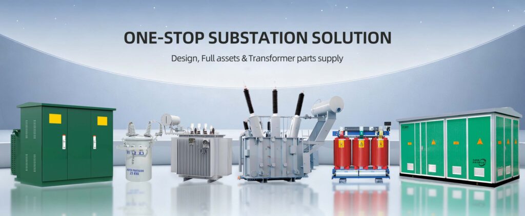
Zisheng are a professional 19+ years manufacturer in producing Oil-Immersed Transformers, Compact Substation, Pad Mounted Transformers, Pole Mounted Transformers and Dry Type Transformers. We own the certificates of ISO/CE/IEC 60076 and TUV Rheinland.
Transformers undergo rigorous FAT and type testing, support voltage/capacity customization. Welcome to consult for Catalog and Product. you can contact us at email [email protected].
+86-191-3128-5373 +86-191-3128-5373 [email protected]