Transformer Auxiliary Power Supply Design for African Industrial Plants

At Zisheng Electric, transformer auxiliary power supply design is reviewed as part of the complete plant control system. The auxiliary system does not carry the main process load, but it keeps protection relays, breaker mechanisms, tap changers, cooling equipment, heaters, battery chargers and communications available when the transformer is energised, tripped or restored.
For African industrial plants, utility interruptions, generator transfer, long cable runs, high ambient temperature, dust and difficult spare-parts logistics can expose a weak auxiliary system quickly. A transformer may have the correct MVA rating and still be difficult to operate if its control power arrangement is not coordinated with the substation.
Why transformer auxiliary power supply design matters
The load list should cover normal operation, transformer energisation, a protection trip and loss of incoming power. Typical loads include protection relays, breaker closing and tripping coils, spring-charging motors, OLTC motors, cooling fans and pumps, oil-temperature and winding-temperature instruments, space heaters, marshalling-box lighting, fire interfaces, RTU or SCADA equipment and battery chargers.
Not every load has the same duty. A trip coil operates for a short pulse, while a heater may run for hours. A fan motor may start at the same time as another auxiliary motor. The charger is continuous, while the battery may supply the entire DC system during loss of AC. The schedule should therefore show continuous power, intermittent power, starting current, duty cycle, voltage, phase, frequency and required backup time. “Auxiliary supply, 20 kVA” is not enough engineering information.
| Design item | Engineering question | Evidence to freeze |
|---|---|---|
| DC control voltage | Can every relay, trip coil and closing coil operate at minimum battery voltage? | Approved protection and control voltage schedule |
| AC auxiliary voltage | Do fans, pumps, heaters and sockets match the plant board? | Motor and heater data with starting current |
| Battery autonomy | How long must protection, trips and communications remain available? | Owner autonomy requirement and load calculation |
| Charger capacity | Can it carry standing load and recharge after discharge? | Charger sizing and recovery-time basis |
| Cable voltage drop | Will the farthest breaker trip reliably during a DC fault? | Control-cable schedule and worst-case calculation |
AC and DC control voltage selection
Many transformer packages use an AC auxiliary board for fans, pumps, heaters and sockets, together with a DC control system for protection and breaker operation. Common project arrangements include 110 VDC or 220 VDC for protection and tripping, with 230 VAC or 400/415 VAC for motors and heaters. These are examples only; the owner and utility specification govern the final choice.
A lower DC voltage can reduce insulation requirements but increases current and voltage drop on long cables. A higher voltage reduces current but requires compatible coils, chargers, fuses and insulation coordination. Confirm voltage at the farthest device, not only at the battery terminals.
Battery and charger redundancy
The battery is the energy source that allows a protective trip to operate after the AC supply collapses. Assess normal continuous load, momentary trip and closing loads, alarm and communication loads, and the specified autonomy period. A charger must carry the standing DC load and provide the required recharge current. If it is sized only for standing load, recovery may take too long.
Critical substations may use two chargers, two battery banks or a dual-DC arrangement. Redundancy is functional only when the sources do not share one small AC feeder, fuse, common control cable or untested changeover contact. Battery chemistry also affects temperature correction, ventilation, maintenance and end-of-life capacity. In hot regions, battery-room temperature and charger compensation deserve specific review.
Generator and utility transfer interfaces
African industrial plants often combine utility supply with diesel generation, captive generation or solar and battery systems. The auxiliary board must be coordinated with the transfer scheme. Confirm whether auxiliary power is available before transformer energisation, whether a generator can start without transformer cooling, and which loads are shed during low voltage or low frequency.
The transfer sequence should identify the incomer, bus coupler, essential-load feeder and transformer auxiliary feeder. Interlocks must prevent unsafe paralleling unless synchronising equipment and operating procedures allow it. For large cooling fans, starting current can cause a voltage dip on a weak generator bus. A staged start, soft starter or variable-speed drive may be suitable, but it must be checked against the required transformer cooling duty.
Environmental and installation factors
High ambient temperature reduces the margin available to motors, chargers, batteries and electronic relays. Dust can block ventilation filters and shorten contactor life. Humidity and condensation can affect marshalling cabinets when night temperature falls rapidly. Coastal projects add salt contamination and corrosion risk.
The specification should state ambient temperature, altitude, humidity, dust exposure, corrosivity, indoor or outdoor installation and enclosure requirements. Outdoor auxiliary panels may need a sun shield, anti-condensation heater, drain arrangement and suitable cable glands. The interface drawing should show lifting points, cable entries, gland plates, earthing points and separation between power, control and communication wiring.
FAT and commissioning evidence
A useful FAT proves the auxiliary system as an operating sequence. Check AC distribution, DC polarity, insulation, charger alarms, battery simulation, trip and close circuits, spring charging, OLTC operation, fan and pump control, heater thermostats, oil-level alarms, Buchholz contacts, pressure-relief contacts, temperature alarms and SCADA mapping.
| Test | Why it matters | Minimum record |
|---|---|---|
| DC trip at minimum voltage | Confirms fault clearing after battery discharge | Coil voltage, operating time and breaker status |
| Charger failure simulation | Verifies alarm and battery takeover | Alarm text, relay indication and time |
| Fan and pump sequence | Confirms cooling starts at the required condition | Thresholds, current and rotation check |
| AC source transfer | Prevents loss of essential controls | Source status, interlock and transfer sequence |
| SCADA point-to-point | Prevents incorrect remote indications | Point list, terminal and verified status |
Procurement checklist for EPC buyers
Before approving the transformer data sheet, request the auxiliary single-line diagram, AC and DC load schedules, battery and charger calculation, control-cable voltage-drop calculation, interface list, cause-and-effect matrix, terminal schedule and FAT procedure. Confirm which components are included in the transformer package and which are supplied by the EPC contractor.
Specify spare ways, spare contacts, test terminals, relay files, recommended spare fuses, charger modules, fan motors, thermostats and communication converters. In remote plants, a small spare can prevent a long outage. Do not accept a generic auxiliary drawing after purchase order; the final design depends on the selected breaker, relay, tap changer, cooling arrangement and transfer scheme.
How Zisheng Electric supports the project
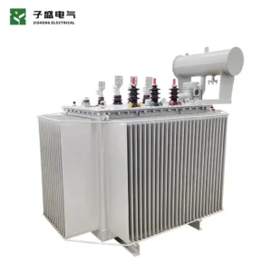
Zisheng Electric coordinates transformer auxiliary power supply design with oil-immersed transformers, dry-type transformers, power transformers, compact substations and MV switchgear. Send us your drawings, datasheets, load list, technical specification, single-line diagram, grid parameters and environmental conditions. Include breaker data, control-voltage standard, battery autonomy, generator arrangement and SCADA point list where available. Our engineering team will return a practical interface and test plan and respond to project inquiries within 24 hours.
For related project context, review transformer protection CT specification and transformer load-shedding interfaces. Product references include the 10MVA 33/11kV oil-immersed transformer and prefabricated substation.
About ZISHENG ELECTRICAL
Zisheng are a professional 19+ years manufacturer in producing Oil-Immersed Transformers, Compact Substation, Pad Mounted Transformers, Pole Mounted Transformers and Dry Type Transformers. We own the certificates of ISO/CE/IEC 60076 and TUV Rheinland.
Transformers undergo rigorous FAT and type testing, support voltage/capacity customization. Welcome to consult for Catalog and Product. you can contact us at email [email protected].