A Comprehensive Analysis of Power Transmission and Distribution: A Systems Engineering Guide from Generation and Step-Up Transmission to Step-Down Distribution
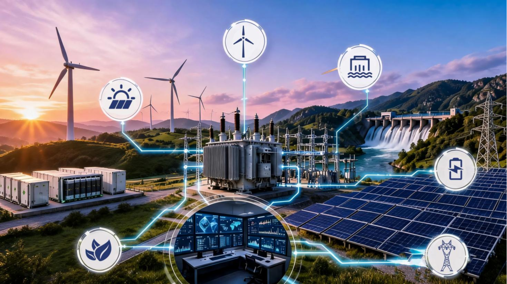
Modern power systems are among the most complex engineering infrastructures ever built by humanity. Every time a switch is flipped, electricity has already traveled hundreds or even thousands of kilometers—passing sequentially through generators, step-up transformers, high-voltage transmission lines, step-down substations, and distribution transformers—before finally reaching the end user. For professionals involved in power system design, equipment procurement, or grid infrastructure planning, understanding this complete end-to-end process is crucial.
This article breaks down the entire process of power delivery into four key stages—generation, transmission, distribution, and consumption—and analyzes the core equipment and technical essentials of each stage.
I. Power Generation: Conversion of Primary Energy into Electrical Energy
It all begins at the power plant. Here, primary energy sources—such as coal, natural gas, nuclear energy, hydropower, wind power, or solar energy—are converted into electrical energy. The core piece of equipment in this process is the generator, which converts mechanical energy into alternating current (AC) through the principle of electromagnetic induction.
Key Data:
A typical 1,000 MW coal-fired power plant generates approximately 8.76 million megawatt-hours (MWh) of electricity annually, enough to meet the yearly electricity needs of about one million households.
Global annual electricity generation has surpassed 30,000 terawatt-hours (TWh), with renewable energy accounting for nearly 30% and growing at an annual rate of 8%–10%.
However, the voltage output from power plants is typically only 10 kV to 20 kV, which is unsuitable for efficient long-distance transmission. At this voltage level, transmission losses over a distance of 100 kilometers can exceed 30%. This is precisely why voltage step-up is the next critical step.
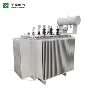
To address the challenge of significant power loss during long-distance transmission at low voltages, large outdoor oil-immersed step-up transformers serve as the core hub equipment for power plants transmitting electricity to the grid. The 10–20 kV low-voltage AC generated by the power plant is fed into the step-up transformer, where electromagnetic conversion via pure copper windings boosts the voltage to the 110 kV or 220 kV extra-high-voltage level; this drastically reduces transmission line losses, enabling the cost-effective, long-distance transport of electrical energy.
II. Power Transmission Stage: Long-distance transmission following voltage step-up
Core Principle: Joule’s Law
According to Joule’s law, power loss in a transmission line is proportional to the square of the current (P = I²R). Under the premise that the transmission power remains unchanged (P = UI), increasing the voltage can reduce the current proportionally – and the line loss decreases significantly with the square level of the voltage.
To ensure the economic viability and feasibility of long-distance power transmission, the current first enters a step-up substation, where power transformers raise the voltage to extra-high or ultra-high voltage levels.
Transmission voltage level system:
| Transmission Level | Voltage Range | Typical Application Scenarios |
|---|---|---|
| Sub-transmission | 35 kV – 115 kV | Regional power distribution |
| High Voltage (HV) | 115 kV – 230 kV | Inter-city power transmission |
| Extra-High Voltage (EHV) | 230 kV – 765 kV | Inter-regional power transmission |
| Ultra-High Voltage (UHV) | 765 kV – 1,100 kV | National grid backbone network |
At the ultra-high voltage (UHV) level, transmission losses can be controlled within the range of 3%–5% per 1,000 kilometers—far lower than the loss levels exceeding 30% found at distribution voltage levels.
Core Equipment: Power Transformer
Large step-up transformers at this stage typically have capacities ranging from 100 MVA to over 1,000 MVA. These transformers are filled with mineral oil, which serves a dual purpose: providing electrical insulation (with a dielectric strength exceeding 60 kV/mm) and facilitating heat dissipation and cooling (with a thermal conductivity of approximately 0.12–0.15 W/m·K). This design enables the power transformers to operate reliably for more than 30 years under sustained high-load conditions.
Once the voltage has been stepped up, the electrical energy feeds into a vast network of high-voltage transmission lines—spanning mountains, rivers, and plains—to complete the long-distance transmission from energy centers to load centers.
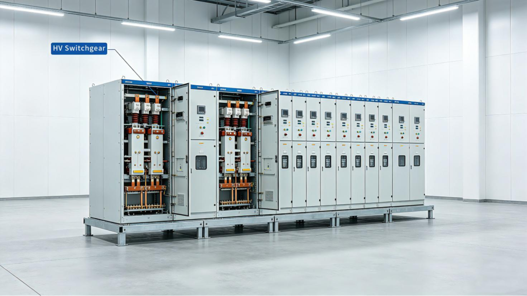
After the transformer steps up the voltage, the electrical energy requires a complete set of high-voltage switchgear to manage circuit switching, fault protection, and safe operation and maintenance. The image below shows standardized high-voltage (HV) switchgear; featuring a neat, modular design that integrates circuit breakers, instrument transformers, and control circuits, this equipment is an essential core component of step-up substations, compatible with transmission systems ranging from 35 kV to 1100 kV.
III. Power Distribution Stage: Step-down transformation at successive levels, extending deep into cities and reaching end-users.
High-voltage electricity cannot be fed directly into homes or factories. It must pass through a series of step-down substations to reduce the voltage in stages to safe, usable levels.
Step-by-step voltage step-down path:
500 kV / 220 kV (transmission voltage)
→ Regional step-down substation
→ 110 kV / 35 kV (regional distribution)
→ Urban step-down substation
→ 10 kV (urban distribution network)
→ Distribution transformer (pole-mounted or pad-mounted)
→ 380 V / 220 V (end-user voltage)
Core Equipment: Distribution Transformers and Combined Unit Substations
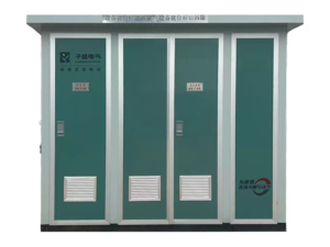
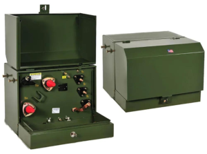
At the final stage of voltage step-down, the distribution transformer—typically integrated into a packaged substation (commonly known as a “box-type substation” or “pole-mounted transformer”)—steps down the voltage from 10 kV to 380 V/220 V for direct use by end-users.
Modular Unit Substations vs. Traditional Substations:
| Comparison Dimension | Traditional Substation | Modular Unit Substation (Box-type Substation) |
|---|---|---|
| Installation Period | 3–6 months | 2–3 days |
| Footprint | Baseline | 40%–60% reduction |
| Factory Prefabrication | No | Yes (Plug-and-play) |
| Protection Rating | Depends on site construction | IP54–IP67 (Factory-sealed) |
| Initial Investment | High | Significantly lower |
Take, for example, a typical 1,000 kVA packaged substation; it can meet the electricity needs of 200–500 households or a medium-sized commercial building. Meanwhile, isolation transformers—widely used in urban distribution networks—achieve electrical isolation between the primary and secondary sides through electromagnetic induction; they effectively suppress harmonics, surges, and ground loop interference, thereby ensuring a secure power supply for sensitive loads such as medical equipment and data center servers.
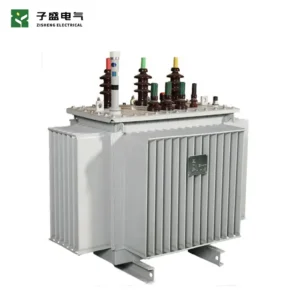
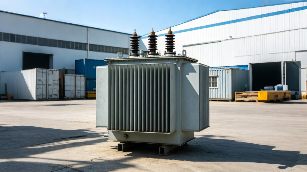
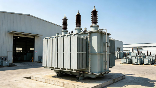
The medium-sized, oil-immersed distribution transformer shown in the factory photo below is the core equipment responsible for the final stage of urban power grid transformation—stepping down voltage from 10kV to 380V/220V. Equipped with multiple high-efficiency cooling fins and robust high-voltage porcelain bushings, the unit is suitable for use in box-type substations and outdoor pole-mounted installations. Its capacity range meets the full spectrum of residential, industrial, and commercial needs. Featuring a high-IP-rated enclosure and a mineral-oil-based insulation and cooling system, it reliably supports step-down power distribution across urban areas and industrial parks, serving as the core transformer unit within modular substations.
IV. Electricity Consumption: End-Use Demand and Emerging Energy Storage Trends
At the point of consumption, electrical energy flows through service lines and meters into countless households, offices, and industrial facilities. At this stage, the electrical energy is converted into various forms of energy suitable for end-use applications:
Electric motor → Mechanical energy (industrial drives, water pumps, compressors)
Lighting systems → Light and thermal energy (LED lights, fluorescent lamps, industrial lighting)
Charging systems → Chemical energy stored in batteries (electric vehicles, UPS, portable devices)
Electric heating elements → Thermal energy (electric stoves, furnaces, water heaters)
Global electricity consumption mix:
| Electricity-consuming Sector | Global Share | Key Application Scenarios |
|---|---|---|
| Industry | Approx. 42% | Motor drives, process heating, variable frequency drives |
| Residential | Approx. 30% | Lighting, home appliances, HVAC |
| Commercial | Approx. 18% | Office equipment, refrigeration, lighting |
| Transportation | Approx. 8% | Electric vehicle charging, rail transport |
| Other | Approx. 2% | Agriculture, mining |
Emerging Trend: Energy Storage Systems on the Consumption Side
With the widespread adoption of electric vehicles and the development of distributed energy resources, the importance of energy storage systems on the demand side is becoming increasingly prominent. Grid-scale battery energy storage systems (BESS) require dedicated energy storage transformers to match voltage levels and provide electrical isolation between battery packs and the grid, thereby ensuring safe and efficient bidirectional energy flow. Industry forecasts indicate that by 2030, charging stations will account for 15%–20% of the growth in electricity demand.
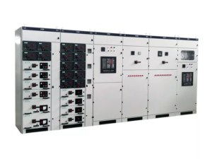
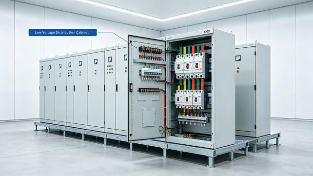
The power distribution and on/off protection of various industrial, commercial, and residential end-loads all rely on low-voltage switchgear to achieve stable power supply. The image below shows our company’s standardized GGD low-voltage switchgear. The cabinet integrates circuit breakers, metering instruments, and standardized copper busbar harnesses.The modular design is suitable for a wide range of applications—from main factory power distribution and office building service entrances to residential terminal distribution—enabling precise control over 380V/220V terminal circuits and providing safe, reliable power distribution solutions for diverse loads such as motors, lighting, and charging equipment.
Summary: A complete power transmission chain.
| Power System Link | Core Equipment | Voltage Change | Key Data |
|---|---|---|---|
| Power Generation | Generator | Output: 10–20 kV | Global annual power generation >30,000 TWh |
| Power Transmission | Step-up Transformer | 10 kV → 220–1,100 kV | Transmission losses: 3%–5% per 1,000 km |
| Power Distribution | Step-down Transformer / Box-type Substation | 110 kV → 10 kV → 380 V | A 1,000 kVA transformer can supply 200–500 households |
| Electricity Consumption | Terminal Electrical Equipment | Input: 380 V / 220 V | Industrial electricity consumption accounts for 42% of global electricity use |
From the burning of coal to the glowing of a filament, from rushing water to the vibration of a mobile phone—electric current completes this complex journey at nearly the speed of light. This represents not only a triumph of physics but also the culmination of the ingenuity and sustained innovation of generations of engineers in the fields of power systems, transformer design, and grid infrastructure.
Frequently Asked Questions (FAQ)
Q: Why must extra-high voltage be used for long-distance power transmission?
According to Joule’s law (P=I²R), line losses are proportional to the square of the current. For a given transmission power, raising the voltage allows the current to be reduced proportionally, thereby cutting losses from over 30% down to 3%–5%.
Q: What role does mineral oil play in transformers?
Mineral oil serves two core functions: electrical insulation (with a dielectric strength of up to 60 kV/mm) and cooling/heat dissipation (with a thermal conductivity of 0.12–0.15 W/m·K), thereby ensuring the transformer’s long-term operation under high loads.
Q: In what scenarios are modular unit substations suitable?
They are suitable for applications requiring rapid deployment and a compact footprint, such as urban distribution networks, residential complexes, commercial complexes, industrial parks, and temporary power supply sites. Their factory-prefabricated, plug-and-play nature allows for significantly shorter construction timelines.
Q: How do energy storage transformers differ from standard transformers?
Energy storage transformers are specifically designed for battery energy storage systems. They must support bidirectional power flow and feature higher levels of electrical isolation as well as a wider voltage regulation range to accommodate voltage fluctuations during the charging and discharging processes of the energy storage system.
About ZISHENG ELECTRICAL
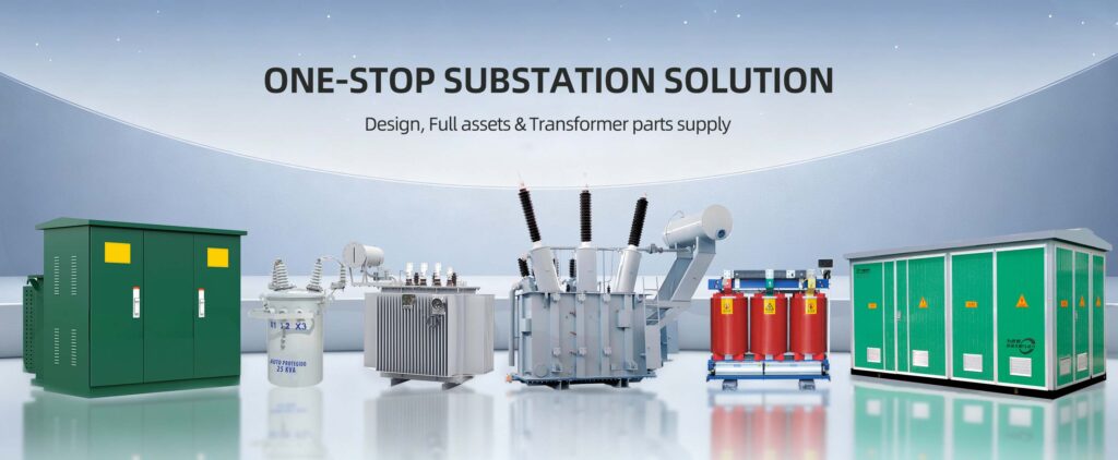
Zisheng are a professional 19+ years manufacturer in producing Oil-Immersed Transformers, Compact Substation, Pad Mounted Transformers, Pole Mounted Transformers and Dry Type Transformers. We own the certificates of ISO/CE/IEC 60076 and TUV Rheinland.
Transformers undergo rigorous FAT and type testing, support voltage/capacity customization. Welcome to consult for Catalog and Product. you can contact us at email [email protected].