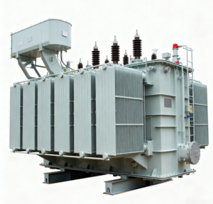
Railway Depot Transformer Specification: Harmonics, Regenerative Loads and Service Continuity
A railway depot transformer is not selected only from the arithmetic sum of workshop loads. A depot combines train maintenance equipment, traction auxiliaries, cranes, compressors, ventilation, battery chargers, lighting, offices and safety systems. Their duty cycles, harmonic spectra, starting currents and continuity priorities are different. An EPC specification must therefore translate the operating plan into electrical design cases before it fixes transformer kVA, impedance or cooling.
This guide explains how to build that specification without assuming that every railway project needs a special traction transformer. The first decision is whether the unit supplies ordinary three-phase depot auxiliaries, a converter-fed traction system, or both through separated electrical zones. Zisheng Electric should receive the single-line diagram, load schedule and network data before confirming a project-specific design.
Define the Electrical Boundary Before Selecting the Transformer
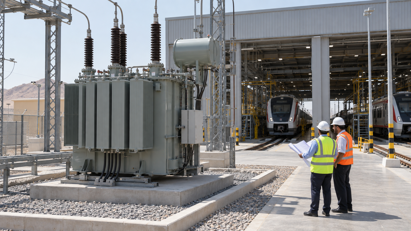
Start by marking the transformer’s actual supply boundary. Station auxiliaries, signaling, depot machinery and traction converters may belong to different systems, earthing arrangements or owners. A transformer serving workshop auxiliaries should not be described as a traction transformer merely because it is installed on railway property. Conversely, a unit directly coupled to rectifiers or inverters requires converter-duty review beyond a conventional distribution load list.
Identify incoming voltage, frequency, maximum and minimum fault level, neutral treatment, cable length, switching arrangement and the intended low-voltage distribution topology. Record whether the depot can be back-fed, whether generators or battery systems can energize the bus, and whether future phases will add trains, workshop bays or charging equipment.
Build an Operating Load Model, Not a Nameplate Total
Separate continuous loads from intermittent and standby loads. Ventilation, pumps and IT systems may operate for long periods; wheel lathes, cranes, welding sets and compressors are cyclic; fire pumps and emergency ventilation may be contingency loads. Apply diversity only when the operating sequence supports it. A diversity factor copied from a commercial-building template can hide simultaneous maintenance activities.
For each large motor, document rated kW, efficiency, power factor, starting method, starts per hour, acceleration time and driven-load torque. Compare the voltage-dip case with the process requirement, contactor ride-through limits and protection settings. Relevant principles are discussed in Zisheng Electric’s water-treatment transformer study, where pump starting and variable-speed drives are coordinated with source strength.
Include Regenerative and Reverse-Power Conditions
Modern drives may return energy during braking or test operation. The EPC team should confirm whether regenerated power is absorbed locally, exported through the transformer, or limited by the converter controls. Bidirectional energy flow does not automatically require a different transformer rating, but it can change protection directionality, voltage control, harmonic conditions and the operating cases used for thermal assessment.
Harmonics Must Be Based on Converter Data
Variable-frequency drives, battery chargers, UPS systems and workshop power electronics produce nonsinusoidal current. Request the manufacturer’s harmonic current spectrum at representative loading points rather than assigning a single total harmonic distortion value to every operating state. The study should include credible combinations of equipment, background voltage distortion and any power-factor correction or harmonic filters.
IEC 60076-1 is the general reference for power transformers and includes definitions related to harmonic content. Where a transformer is directly associated with semiconductor converters, the project should determine whether the relevant parts of IEC 61378 apply. Standards and editions should be confirmed through the official IEC 60076-1 page and the IEC Webstore; the specification must not claim compliance without a documented applicability review.
Harmonics increase winding and structural losses and may raise neutral current where triplen components exist. Specify the spectrum, loading duration, ambient profile and permissible temperature rise so the manufacturer can assess thermal duty. Compare the approach with this transformer harmonic-loading guide.

Engineering Decision Table
| Decision | Required project input | Acceptance check |
|---|---|---|
| Transformer rating | Time-based load schedule, diversity and future phases | Continuous and contingency loading remain within agreed thermal limits |
| Impedance | Source fault level, motor starts and LV fault duty | Balances voltage dip and switchgear withstand |
| Winding duty | Converter topology and harmonic spectrum | Supplier thermal assessment uses stated operating cases |
| Redundancy | Critical-load list and maintenance philosophy | Loss of one unit does not interrupt designated essential services |
| Cooling | Hourly ambient profile, enclosure and ventilation | Rating basis matches the installed environment |
| Earthing | Railway EMC plan and protection philosophy | Neutral and bonding arrangement are coordinated across interfaces |
| FAT evidence | Data sheets, drawings and approved standards | Results are traceable to the ordered design and serial number |
Choose Impedance Through a System Study
Higher impedance reduces prospective short-circuit current but increases voltage drop during motor starting and load steps. Lower impedance improves voltage stiffness but may raise switchgear duty. Specify impedance at the rated frequency, principal tap and reference temperature, then define tolerances and any tap-dependent study cases. The purchaser should provide maximum and minimum source fault levels rather than forcing the supplier to guess the upstream network.
IEC 60076-5 addresses a transformer’s ability to withstand external short-circuit overcurrents and describes thermal and dynamic verification approaches. Use the official IEC 60076-5 publication page to confirm scope and edition. System protection, conductor withstand and breaker clearing times remain project responsibilities.
Design Service Continuity Around Critical Loads
A depot may tolerate interruption to some workshop tools but not to fire systems, signaling interfaces, security, emergency lighting, drainage or controlled train movements. Classify loads by allowable interruption time and restoration method. Then compare one transformer with sectionalized buses, two transformers with an open or closed tie, and local UPS or generator support for no-break loads.
N+1 capacity is meaningful only when the remaining transformer, bus coupler, cables and ventilation can carry the defined contingency load. Include maintenance isolation, protection selectivity and common-mode failures. The principles in the African data-center transformer article provide a useful comparison for redundancy, but railway load priorities must be defined independently.
Coordinate Earthing, EMC and Protection Interfaces
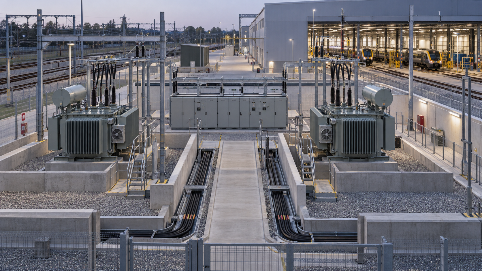
Railway projects can contain traction return circuits, signaling earths, protective conductors and building lightning-protection systems. The transformer specification should reference the project earthing and electromagnetic-compatibility plan without inventing a universal bonding arrangement. Define the winding connection, neutral terminal rating, earthing method and responsibility for neutral grounding equipment.
Protection inputs normally include transformer rating, ratio, vector group, impedance, CT ratios, source fault levels and the expected energization current. Coordinate differential, restricted earth-fault, overcurrent, earth-fault and temperature functions with upstream and downstream devices. If medium-voltage distribution is included, interface the transformer with the project’s 3 kV–10 kV switchgear rather than treating the two packages independently.
Select Indoor or Outdoor Construction from the Site
Indoor electrical rooms require fire strategy, access, drainage, ventilation and acoustic review. Outdoor units require weather, pollution, corrosion, solar radiation and security inputs. Do not state a generic maximum ambient temperature when the hourly profile and enclosure ventilation determine the real thermal duty. Coastal or dusty depots may need coating, filtration and maintainability provisions.
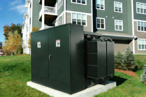
A compact auxiliary substation may use a dry-type transformer where the verified installation and fire strategy support it. Higher-voltage outdoor supplies may use a project-specific 35 kV–46 kV power transformer. These are application routes, not automatic selections; voltage, capacity, loss evaluation and national rules must be confirmed.
Acoustic Limits Need a Measurement Basis
Depots near residences or offices should state whether the limit applies to transformer sound power, sound pressure at a defined distance, or the complete substation at the property boundary. Include cooling equipment and tonal characteristics where required. A site noise model may be necessary because building reflections, barriers and multiple sources affect the measured result.
Specify the Data Package and Design Reviews
Require a completed data sheet, guaranteed particulars, outline and foundation drawings, terminal details, mass and oil data where applicable, cable-box drawings, control schematics, loss capitalization inputs, noise data, coating system, routine-test schedule and deviations list. Harmonic and thermal studies should identify the model, assumptions, spectra and duty cycle.
Hold interface reviews at bid clarification, basic design and final design. Freeze cable entry, clearances, CT locations, auxiliary supplies, alarm contacts and communication mapping before manufacturing release. Any later change to converter rating, operating sequence or source fault level should be screened for its effect on transformer duty and protection.
Factory Acceptance and Site Readiness
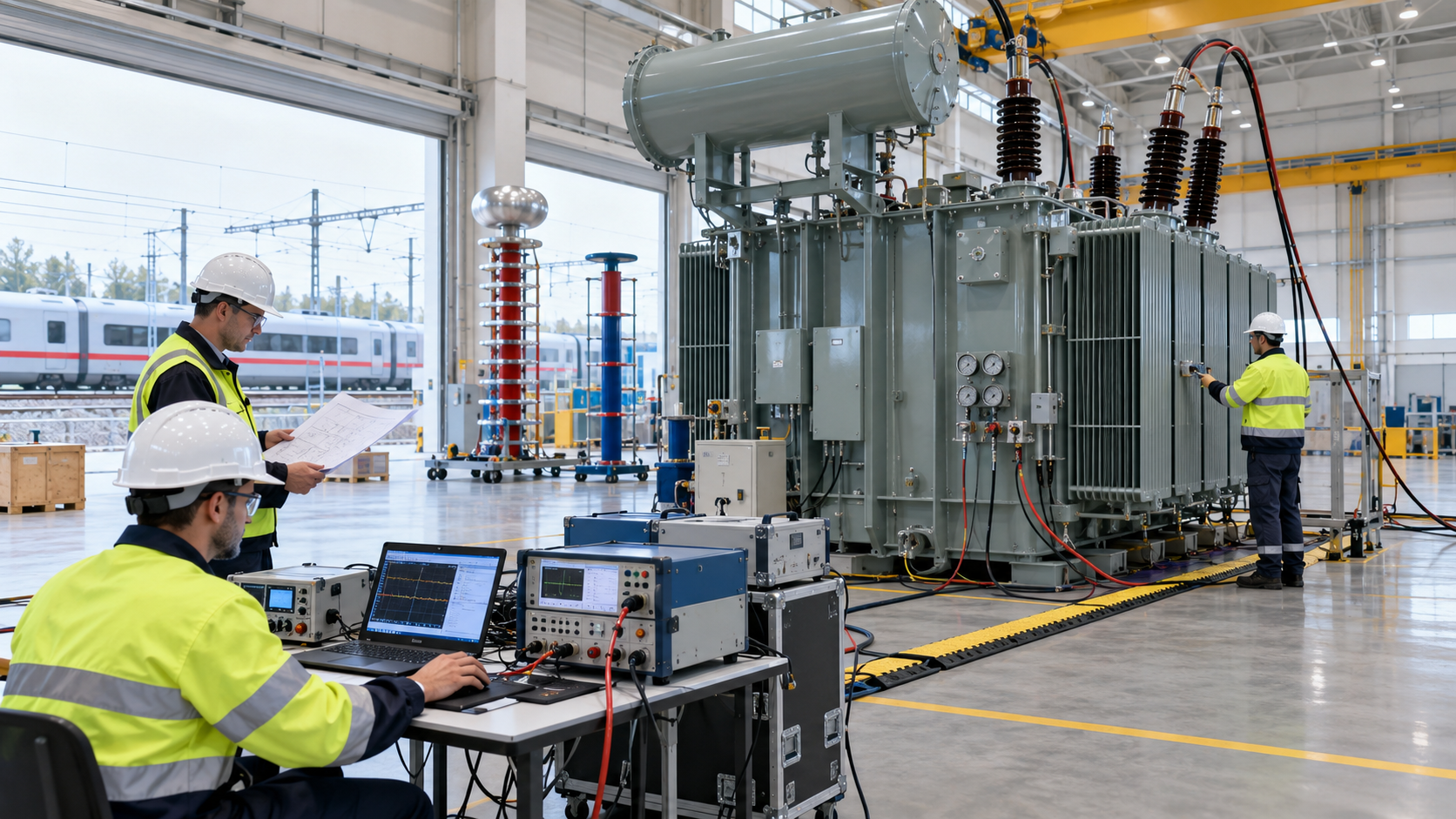
The FAT plan should reference the applicable standard and approved drawings, identify routine tests, document calibrated instruments and state how results are corrected to reference conditions. Review ratio, polarity, winding resistance, impedance, load loss, no-load loss and current, dielectric tests and functional checks as applicable to the ordered design. Special tests should be specified before contract award, not requested after manufacturing.
The purchaser should also reconcile the FAT report with the final data used by the system study. A compliant test value can still require a study update when it differs materially from a preliminary assumption. Record final impedance, vector group, tap range, auxiliary burden and CT data in the protection handover package. Photograph terminal markings and accessory nameplates, and close every punch-list item through an agreed concession or corrective-action process.
Before energization, confirm transport inspection, foundation level, earthing, cable terminations, oil level or enclosure condition, cooling circuits, CT wiring, protection settings, alarms, interlocks and phase sequence. Capture baseline insulation and diagnostic results required by the owner. First energization should follow an approved method statement and disturbance records should be reviewed.
Plan Maintainability Before Layout Freeze
Transformer availability is influenced by access as much as electrical rating. Confirm removal routes for fans, bushings or enclosure panels, safe working clearances, lifting points, oil-processing connections where applicable and space for test equipment. Locate indicators and sampling points where technicians can reach them without entering an unsafe zone. The spare-parts list should follow the owner’s restoration target and installed fleet, not a generic catalogue package.
Procurement Checklist
- Define auxiliary, converter-fed and traction-system boundaries.
- Provide time-based loads, motor starts and future phases.
- Issue harmonic spectra and regenerative operating cases.
- State maximum and minimum source fault levels.
- Classify essential loads and permitted interruption times.
- Coordinate impedance with voltage dip and breaker duty.
- Define earthing, EMC and protection responsibilities.
- State ambient, enclosure, corrosion and acoustic conditions.
- List drawings, studies, FAT records and revision milestones.
- Approve the commissioning and first-energization plan.
Convert the Railway Operating Plan into Transformer Requirements
A defensible railway depot transformer specification connects the timetable and maintenance workflow to electrical duty. It distinguishes ordinary auxiliaries from converter duty, models harmonics and motor starting, assigns continuity classes and closes every interface before manufacturing. This gives the supplier enough information to design and price the required transformer without adding unsupported assumptions.
Send Zisheng Electric the single-line diagram, voltage ratio, load schedule, converter data, ambient profile and continuity philosophy for an engineering review. Our engineering team will review the requirements and respond to project inquiries within 24 hours.
About ZISHENG ELECTRICAL
Zisheng are a professional 19+ years manufacturer in producing Oil-Immersed Transformers, Compact Substation, Pad Mounted Transformers, Pole Mounted Transformers and Dry Type Transformers. We own the certificates of ISO/CE/IEC 60076 and TUV Rheinland.
Transformers undergo rigorous FAT and type testing, support voltage/capacity customization. Welcome to consult for Catalog and Product. you can contact us at email [email protected].