Transformer Harmonic Loading for Zambia Copper Processing Plants: Rectifiers, Drives and Thermal Margin
Zisheng Electric treats transformer harmonic loading as a design input, not a label added to a conventional transformer quotation. In a Zambia copper-processing plant, rectifiers, variable-speed drives, furnace auxiliaries, large motors and power-factor correction equipment can operate on the same internal network. The resulting current waveform, loading cycle and switching conditions affect transformer heating, voltage distortion, protection behaviour and the useful margin available for production expansion.
This guide is written for EPC engineers and industrial procurement teams preparing a transformer specification for a new concentrator, smelter auxiliary system, refinery process line or plant expansion. It does not assume one national voltage, one utility interface or one harmonic limit. Those values must come from the approved point-of-connection study, owner requirements and site measurements.
Why Transformer Harmonic Loading Changes the Design Basis
A transformer is normally rated by apparent power under defined service conditions, but RMS current alone does not describe how nonsinusoidal current distributes losses. Higher-frequency components can increase winding eddy-current losses and structural stray losses. They may also increase neutral current in four-wire systems, excite resonances with capacitor banks and create additional voltage distortion across system impedance.
The first procurement risk is therefore false simplicity. A load list may show 4,000 kW and an acceptable power factor, while the rectifier package produces a current spectrum that creates more heating than a comparable linear load. Selecting only from total kVA can leave the transformer with insufficient thermal margin. Conversely, applying a generic oversizing percentage without a study can raise cost while leaving the actual resonance or protection issue unresolved.

Separate load classes before calculating duty
Group loads by how they draw current and how they operate. Typical groups include direct-on-line motors, variable-speed drives, six-pulse or twelve-pulse rectifiers, induction or resistance furnaces, welding loads, lighting, UPS systems and general auxiliaries. For each group, record operating kW, power factor, efficiency, expected simultaneous demand, starting method and available harmonic data.
Do not combine installed capacity with operating capacity. A standby pump should not be counted as a continuous process load if interlocking prevents simultaneous operation, while an expansion feeder should not be ignored if the transformer is expected to support the next production stage.
Transformer Harmonic Loading Input Table for Procurement
| Project input | Transformer decision affected | Why it matters | Check before bid release |
|---|---|---|---|
| Fundamental RMS current by operating case | Base kVA and winding current | Defines continuous electrical duty | Use process operating cases, not only connected load |
| Individual harmonic current spectrum | Winding conductor arrangement and loss allowance | Higher-order current can increase eddy and stray losses | Obtain spectrum at the transformer terminals or an agreed study basis |
| Total harmonic distortion and background voltage distortion | System study and voltage-distortion assessment | Source distortion and load distortion combine through network impedance | State the point of evaluation and measurement method |
| Rectifier pulse number and phase-shift arrangement | Winding quantity, vector relationship and terminals | The converter topology may require dedicated secondaries | Coordinate with the converter supplier |
| Capacitor banks or filters | Resonance review and switching duty | Incorrect tuning can amplify rather than reduce distortion | Provide bank steps, reactor data and switching sequence |
| Ambient temperature, altitude and ventilation | Cooling and temperature-rise margin | Environmental conditions affect heat rejection and insulation clearances | Use verified site values |
| Short-circuit level and transformer impedance | Fault duty, voltage regulation and distortion | Impedance influences both current limitation and voltage drop | Study maximum and minimum source conditions |
| Future process stage | Thermal and connection allowance | Expansion may change both magnitude and spectrum | Define the expansion load by type and date |
Coordinate the Transformer with Rectifiers and Drives
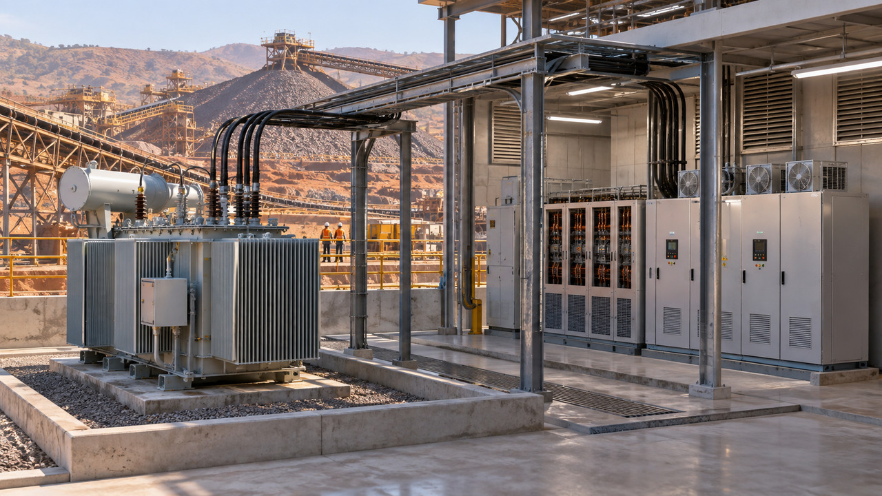
A rectifier transformer cannot be specified independently from the converter. The EPC package should identify pulse number, bridge arrangement, phase displacement, secondary voltages, commutation characteristics, expected overload cycle and whether the converter vendor has a preferred transformer design basis. If multiple converters are intended to provide harmonic cancellation, their operating simultaneity and phase relationships must be confirmed.
Variable-speed drives create a different interface. The transformer specification should identify drive front-end technology, input reactors, DC-link chokes, switching arrangement and the manufacturer’s predicted input current spectrum. A phrase such as “VFD suitable” is not an engineering acceptance criterion. It does not define the current waveform, required thermal allowance or the location where distortion is assessed.
Use dedicated windings where the process requires them
Dedicated secondary windings can isolate converter groups, support phase-shift arrangements and simplify protection boundaries. They also increase terminal, cable and mechanical complexity. Confirm secondary current, phase displacement, insulation level, cable-entry direction, conductor forces and temperature monitoring before the general arrangement is frozen.
If standard distribution loads share the transformer with nonlinear process loads, assess whether the common bus exposes sensitive auxiliaries to unacceptable distortion. A separate auxiliary transformer may offer a cleaner and more maintainable solution than increasing one transformer’s rating.
Thermal Margin Must Follow the Operating Cycle
Copper processing loads are rarely flat. Crushing and conveying may start in sequence; pumping duty changes with process conditions; rectifier output follows production rate; and maintenance states can transfer loads between bus sections. The transformer thermal review should therefore include normal production, maximum credible production, start-up, reduced-operation and contingency cases.
Ambient conditions matter at the same time. The bidder needs the site maximum temperature, daily average, altitude, dust exposure, solar loading for outdoor equipment and ventilation data for indoor rooms. Zambia contains varied elevations and climates, so country-level assumptions are not sufficient. The project’s own meteorological and civil inputs must govern.
For oil-immersed equipment, review whether ONAN cooling is sufficient or whether staged fans are justified. For dry-type equipment, confirm room air paths, enclosure losses, fan-control logic and the consequences of filter blockage. Cooling auxiliaries should be included in the plant reliability and maintenance plan.
Impedance Links Harmonics, Fault Current and Motor Starting
Transformer impedance is a three-way trade-off. Higher impedance can reduce prospective fault current, but it increases voltage drop during motor starting and can contribute to harmonic voltage distortion. Lower impedance supports voltage regulation but raises switchgear fault duty. The correct value comes from a system study, not a copied catalogue percentage.
Model the maximum utility fault level, minimum source condition, generator-supplied case if applicable, largest motor start and nonlinear load operation. Verify that protection remains sensitive under weak-source conditions and adequately rated under strong-source conditions. Coordinate the study with the plant’s rectifier-transformer procurement guidance and the existing article on transformer voltage regulation for African industrial plants.
Power-Factor Correction and Filters Need a Shared Review
Power-factor correction can reduce fundamental reactive current, but capacitors interact with transformer and network inductance. If resonance is near a significant harmonic order, current or voltage may be amplified. Record capacitor-bank kvar, number of steps, reactor percentage, switching device, control method and expected operating combinations.
Where passive or active filters are proposed, define their connection point, design spectrum, operating range and failure response. The transformer supplier needs to know whether the filter is essential to the promised thermal duty or power-quality result. If the transformer can only meet temperature limits while a filter is operating, that dependency belongs in the operating philosophy and alarm system.
Protection, Monitoring and Neutral Design
Nonlinear loads can influence protection measurements and transformer condition monitoring. Confirm that CT performance, relay sampling and metering are suitable for the waveform and expected frequency range. Protection settings should be based on study results and transformer withstand, not adjusted simply to avoid nuisance trips.
For low-voltage four-wire systems, calculate triplen harmonic contribution and neutral current rather than assuming the neutral carries only unbalance. Specify neutral conductor size, bushing rating, earthing arrangement and CT location. For converter transformers with unusual vector groups or multiple secondaries, provide a complete protection-zone drawing.
FAT Evidence for Harmonic-Duty Transformers
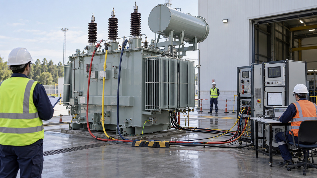
Factory acceptance testing does not normally recreate the complete plant harmonic spectrum. Its value is to confirm the manufactured transformer matches the approved design and to establish traceable routine-test results. The FAT plan should cover winding resistance, ratio and phase displacement, impedance and load loss, no-load loss and current, dielectric routine tests, functional checks of cooling controls, alarms and monitoring, and verification of terminals and nameplate data.
Where the design uses special windings, phase shifts, multiple secondaries or additional temperature sensors, include specific drawing and functional checks. Review test connections and acceptance criteria before the witness date. The final report should identify the tested serial number, tap position, reference temperature and any agreed correction method.
Example procurement statement — hypothetical only
Hypothetical example: “The transformer shall supply a copper-processing bus containing rectifier and variable-speed-drive loads. The purchaser will provide fundamental load, individual harmonic current spectrum, converter topology, capacitor and filter data, ambient temperature, altitude and network short-circuit levels. The bidder shall state the design method used to account for harmonic-related winding and structural losses, the continuous rating under the stated spectrum, cooling duty, winding temperature-monitoring arrangement and any operating limitations. Final impedance and protection inputs are subject to approved system studies.”
This example is a specification format, not a real project record and not a substitute for the actual converter-vendor data.
Site Verification Before Energization
At site, confirm cable phasing, earthing, CT polarity, fan supply, alarm mapping and filter or capacitor-bank settings before introducing nonlinear load. Record baseline voltage and current distortion at agreed points during light load and stepped production states. Compare measured current with the study assumptions. Unexpected distortion should trigger a structured review of load operation, filter status, measurement configuration and system impedance.
Maintenance teams also need practical access to radiators, fans, bushings, cable boxes and monitoring devices. Dust management, ventilation cleaning and periodic thermography should be aligned with the plant environment and operating criticality.
Commission the load in controlled steps
Where the process permits, energize auxiliaries first, then introduce converter and drive groups in planned stages. At each stage, record transformer current, voltage, temperature indications, cooling status and harmonic measurements at the agreed point. The purpose is not to prove compliance from a single short snapshot; it is to confirm that the installed network behaves consistently with the study and that no unexpected resonance, load imbalance or control interaction appears.
Define hold points before commissioning. An unexplained rise in a dominant harmonic, abnormal neutral current, unstable capacitor switching or rapid temperature increase should pause the next load step. The EPC team should compare instrument configuration, filter status, plant topology and study assumptions before changing transformer taps or protection settings. This disciplined sequence protects the transformer and produces a useful operating baseline for future production increases.
Specify the Duty, Not a Generic “Harmonic Transformer”
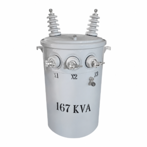
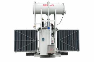
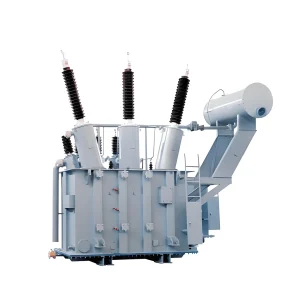
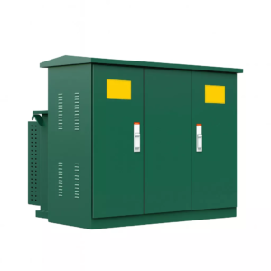
A dependable transformer harmonic loading specification connects the process equipment, network model, transformer thermal design, protection, cooling, FAT and commissioning measurements. Zisheng Electric can review oil-immersed transformer and substation-transformer configurations for industrial projects; see the verified oil-immersed transformer range and substation transformer options.
For an engineering review, provide the single-line diagram, transformer datasheet, complete load list, converter and drive data, harmonic spectrum, capacitor or filter details, utility short-circuit levels, site temperature and altitude, installation layout and operating cases. “Our engineering team will review the requirements and respond to project inquiries within 24 hours.”
About ZISHENG ELECTRICAL
Zisheng are a professional 19+ years manufacturer in producing Oil-Immersed Transformers, Compact Substation, Pad Mounted Transformers, Pole Mounted Transformers and Dry Type Transformers. We own the certificates of ISO/CE/IEC 60076 and TUV Rheinland.
Transformers undergo rigorous FAT and type testing, support voltage/capacity customization. Welcome to consult for Catalog and Product. you can contact us at email [email protected].