Transformer Voltage Regulation for African Industrial Plants: Tap Range, Impedance and Motor Starting
Zisheng Electric approaches transformer voltage regulation for African industrial plants as a system-design question, not a simple tap-setting decision. The transformer must keep utilization voltage within acceptable limits while the incoming supply changes, large motors start, production lines cycle, generators transfer, and the plant grows. A nominal ratio that looks correct on a data sheet can still produce poor operating voltage if impedance, feeder drop, load power factor, tap range, and source conditions are not evaluated together.
Why Voltage Regulation Becomes a Procurement Issue
Industrial plants rarely operate at one steady load. Crushers, pumps, compressors, mills, refrigeration systems, furnaces, conveyors, and variable-speed drives create different operating states. The network may also include utility supply, captive generation, solar generation, or standby generators. Each source has a different short-circuit strength and voltage behavior. A transformer selected only from the installed kW total may therefore deliver acceptable voltage in one condition and unacceptable voltage in another.
Voltage that is too low can reduce motor torque, increase current, extend acceleration time, and cause contactors or electronic loads to drop out. Voltage that is too high can increase stress on insulation and connected equipment. Frequent manual tap changes are not a substitute for a coordinated design. The procurement specification should state the operating cases, allowable utilization-voltage range, source variation, and expected control method.
Start with the Source and Load Data
The transformer supplier cannot evaluate regulation accurately without a defined electrical basis. The EPC team should provide the nominal and expected minimum and maximum primary voltage, system frequency, available fault level, upstream feeder length, conductor data, load schedule, power factor, motor-starting method, harmonic sources, and future load allowance. Where utility information is provisional, the specification should identify assumptions that must be confirmed before design release.
For facilities with standby generation, provide generator rating, transient reactance data when available, voltage-regulator behavior, permitted step load, and the intended load-transfer sequence. A transformer that performs well on a stiff utility source can experience a larger voltage dip when supplied by a smaller generator.
Data required for a practical voltage study
| Input | What to specify | Why it matters | Risk if omitted |
|---|---|---|---|
| Primary supply | Nominal, minimum and maximum voltage; frequency; fault level | Defines available voltage and source stiffness | Incorrect tap center or underestimated voltage dip |
| Transformer | kVA/MVA, ratio, vector group, impedance, losses, tap range | Sets steady-state and transient voltage behavior | Uncomparable bids and study mismatch |
| Feeders | Length, size, material, arrangement and temperature basis | Determines cable or bus-duct voltage drop | Transformer blamed for downstream feeder losses |
| Motors | Rated kW, starting current, power factor, starting method and sequence | Defines the largest transient demand | Failed starts or nuisance tripping |
| Nonlinear loads | Drive, rectifier, UPS and harmonic spectrum data | Affects current, heating and waveform quality | Unexpected losses and voltage distortion |
| Operating cases | Normal, peak, startup, emergency, generator and future states | Prevents design around one convenient snapshot | Acceptable voltage only in normal operation |
Separate Transformer Regulation from System Voltage Drop
Purchasers often use “transformer regulation” to describe every voltage change between the utility connection and the process load. The engineering review should separate the transformer’s internal voltage drop from the drop in upstream and downstream conductors. Transformer impedance and load power factor determine the internal component; feeder resistance and reactance add another component. Source variation and generator response add further movement.
This separation matters because the remedies are different. Changing the transformer tap can correct the steady no-load or average voltage, but it cannot eliminate a large dynamic dip caused by motor acceleration. Increasing cable size may reduce feeder drop but will not correct an unsuitable transformer ratio. A stronger starting method or staged motor sequence may be more effective than oversizing the transformer.
How Tap Range Should Be Specified
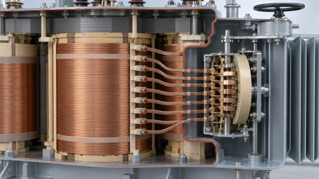
A tap changer alters the effective turns ratio. The specification should identify whether the project requires off-circuit taps or an on-load tap changer, the total range, step size, normal position, control philosophy, and any remote or automatic functions. Off-circuit taps require the transformer to be de-energized before changing position. They suit systems where the supply voltage is relatively stable and adjustment is infrequent. On-load tap changing may be considered when continuous regulation is required, but it adds controls, maintenance requirements, interfaces, and cost.
The tap range should be centered on the actual expected primary voltage, not copied from an unrelated project. A wide range does not guarantee good regulation if the normal tap is wrong or if the step size is too coarse. Review whether every tap position remains compatible with flux-density limits, insulation requirements, available through current, and the system study.
Impedance Connects Regulation and Fault Duty
Transformer percentage impedance has two major consequences. It contributes to voltage drop under load, and it limits short-circuit current. A lower impedance can improve voltage performance and motor starting, but it can raise the required interrupting capacity of switchgear and increase mechanical short-circuit stress. A higher impedance can reduce fault current but cause greater voltage drop and weaker motor-starting performance.
Compare bidder values on the same rating, winding pair, tapping position, and reference basis. For parallel transformers, ratio, vector group, polarity, impedance magnitude, impedance angle, and tap position must support acceptable load sharing. Do not specify a preferred impedance without checking the short-circuit and load-flow studies.
Motor Starting Is Usually the Critical Case
Large induction motors can draw several times rated current during acceleration, depending on motor design and starting method. The exact current and duration should come from the motor and driven-equipment data rather than a generic assumption. Direct-on-line starting normally produces the highest electrical demand. Star-delta, autotransformer, soft-starter, or variable-frequency-drive arrangements change both the current profile and acceleration torque.
The study should test the largest credible motor start with existing loads already connected. Check voltage at the transformer secondary, motor terminals, control circuits, and other sensitive buses. Confirm that the motor develops enough accelerating torque throughout the start and that protection does not trip unnecessarily. If several motors may restart after an outage, define a sequenced restart instead of assuming simultaneous acceleration.
Generator Supply Requires a Separate Study Case
A standby generator is generally a weaker source than the utility network. Starting a large motor after transfer can create a generator voltage and frequency excursion even when transformer capacity is adequate. The transformer’s magnetizing inrush may also influence the restoration sequence. The EPC design should coordinate transformer energization, generator loading, motor restart, and automatic transfer controls.
Ask the generator supplier for permitted step-load and motor-starting performance. Avoid claiming that a transformer tap change will solve a generator transient. The solution may involve preloading limits, reduced-voltage starting, sequential restoration, a different transformer impedance, or a larger generator.

Harmonics Change the Current, Not Just the Waveform
Variable-frequency drives, rectifiers, UPS systems, and similar equipment draw nonsinusoidal current. The RMS current and harmonic spectrum can increase winding eddy-current and structural stray losses. Harmonic voltage drop across system impedance can also affect waveform quality. The procurement package should provide the estimated harmonic load and any required distortion study.
Do not use a vague “VFD compatible” statement as an acceptance criterion. Define the load composition, spectrum or design method, temperature basis, neutral-current conditions where relevant, and required monitoring. The transformer design, feeder arrangement, power-factor correction, and filtering strategy should be reviewed together.
Ambient Temperature and Altitude Affect the Margin
Many African industrial sites combine high ambient temperature, dust, solar exposure, or elevated altitude. These conditions can reduce cooling performance or affect external insulation and clearances. The bidder should state the design ambient temperature, altitude, enclosure or installation arrangement, cooling method, and any applied correction. Project requirements should use verified site data rather than a generic continental assumption.
Temperature margin matters because loading, losses, cooling performance, and insulation aging are connected. Oversizing solely to compensate for uncertain conditions can create unnecessary cost and higher no-load loss. The better approach is to define the environment, operating profile, and required thermal performance clearly.
Coordinate Protection and Voltage Controls
Transformer taps, automatic voltage regulators, capacitor banks, generators, solar inverters, and plant controls can interact. The protection study should consider minimum and maximum fault levels, transformer inrush, motor-starting current, earth-fault paths, and the selected vector group. Control circuits must remain energized during the permitted voltage dip.
If an on-load tap changer is specified, define voltage-sensing location, deadband, time delay, line-drop compensation if applicable, blocking conditions, parallel-control method, alarms, and communications. Without a control philosophy, bidders may price different functions under the same equipment description.
Use FAT to Confirm the Design Basis
Factory acceptance testing cannot reproduce the complete site network, but it can verify transformer parameters used in the studies. The agreed FAT scope should identify applicable routine tests and any specified additional tests, acceptance criteria, witness points, report format, and treatment of deviations. The contractual specification should reference the applicable edition of IEC 60076 or another project standard without assuming that one general citation defines every test and limit.
Ratio measurement, winding resistance, impedance and load-loss measurement, no-load loss and current, insulation tests, functional checks, and accessory verification may be relevant depending on transformer type and contract. The final test results should be compared with guaranteed values and fed back into protection or load-flow studies when the project requires it.
Hypothetical Specification Example
This is a hypothetical specification example, not a real Zisheng Electric project.
A process plant is supplied from a medium-voltage utility feeder and has a standby generator for essential services. One large pump is the dominant starting load. Instead of specifying only transformer kVA and nominal ratio, the purchaser provides utility voltage limits, generator operating data, existing running load, pump starting current and time, feeder impedance, permissible bus-voltage dip, ambient temperature, altitude, harmonic load share, and future expansion.
The bid evaluation then compares each offered transformer at the same operating points. One offer may use lower impedance to support motor starting, but the resulting fault current must remain within switchgear duty. Another may use a wider tap range, but only off-circuit adjustment is offered. A third may propose an on-load tap changer, which requires additional controls and maintenance. The correct choice depends on the study and operating philosophy, not on the largest feature list.

Purchasing Checklist
- Provide minimum, nominal and maximum source voltage and the available short-circuit level.
- State every normal, startup, emergency, generator and expansion operating case.
- Define transformer rating, ratio, vector group, impedance and required tap arrangement.
- Submit large-motor starting data, sequence and acceptable voltage-dip criteria.
- Identify VFD, rectifier, UPS and other nonlinear loads.
- Provide feeder lengths, sizes and installation conditions.
- Confirm ambient temperature, altitude, contamination and enclosure requirements.
- Coordinate voltage regulation with switchgear fault duty and protection settings.
- Agree FAT scope, guaranteed values, document schedule and interface drawings before award.
- Record all assumptions and deviations in the technical bid evaluation.
Information to Send Zisheng Electric
Useful related guidance includes our articles on South Africa industrial transformer tender review, Kenya hospital transformer procurement, and transformer procurement for Nigerian industrial plants. Relevant equipment references include the 10 MVA 33/11 kV oil-immersed power transformer, 66 kV three-phase oil-immersed transformer, and 400 kVA oil-immersed transformer.
For a review of transformer voltage regulation for African industrial plants, send the single-line diagram, load schedule, motor list, source-voltage limits, short-circuit study assumptions, feeder data, generator information, harmonic load details, site conditions, transformer specification, and required FAT scope. Our engineering team will review the requirements and respond to project inquiries within 24 hours.
About ZISHENG ELECTRICAL
Zisheng are a professional 19+ years manufacturer in producing Oil-Immersed Transformers, Compact Substation, Pad Mounted Transformers, Pole Mounted Transformers and Dry Type Transformers. We own the certificates of ISO/CE/IEC 60076 and TUV Rheinland.
Transformers undergo rigorous FAT and type testing, support voltage/capacity customization. Welcome to consult for Catalog and Product. you can contact us at email [email protected].