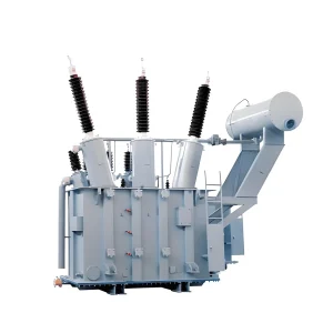
IEC Transformer Manufacturing Process: Oil Immersed Transformer Production Guide
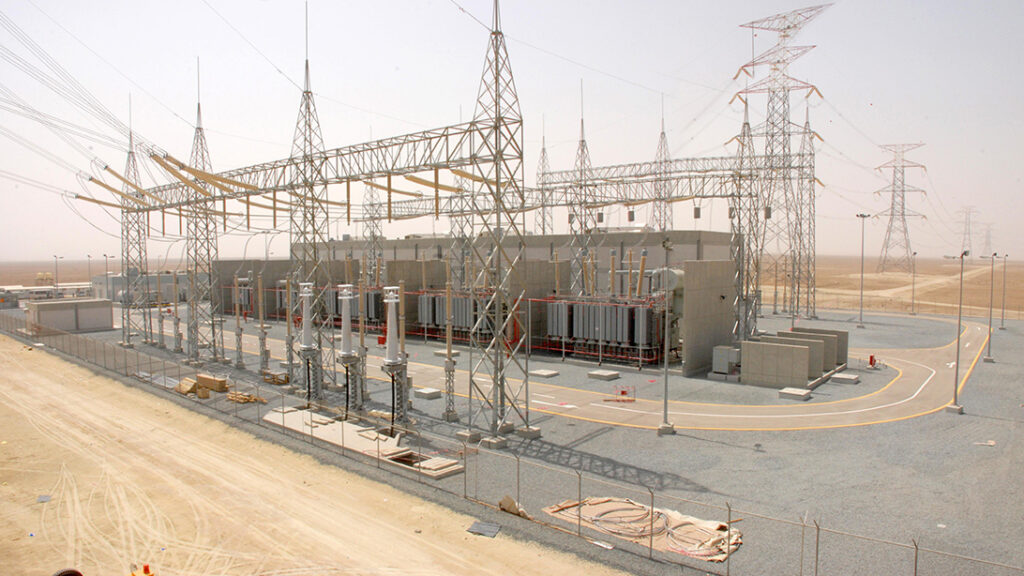
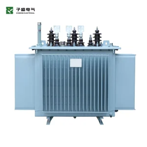
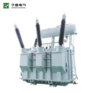
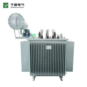
I am an engineer from the transformer design team at Zisheng Electric, specializing in the design and manufacturing of oil-immersed power transformers, high-voltage transformers, and grid project solutions.
Over the years, I have participated in technical support for multiple 110kV/132kV transformer projects, covering design review, technical clarification, manufacturing coordination, and project execution support.
For EPC projects, the manufacturing process of oil-immersed power transformers, Factory Acceptance Testing (FAT), and compliance with IEC 60076 standards are among the most important evaluation factors when selecting a transformer supplier. The IEC 60076 series provides requirements and test methods related to power transformer design, performance, and verification.
You may be searching for a reliable supplier, comparing technical bids, or simply trying to understand one question:
When a transformer manufacturer claims IEC compliance, is the transformer really designed and manufactured according to the standard requirements step by step?
Regardless of your reason for reading this article, I will explain the answer from three perspectives:
- Transformer manufacturing process
- Key quality control points
- IEC 60076-related requirements
A complete oil-immersed power transformer goes through more than ten major manufacturing stages and hundreds of control points, from incoming raw materials to final testing, packaging, and shipment.
Each stage corresponds to specific requirements within the IEC 60076 standard series, including design verification, temperature performance, insulation requirements, and routine testing procedures.
I will focus on the key parts that truly determine transformer reliability.
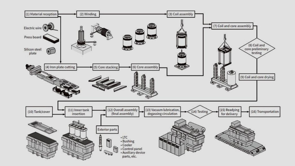
First, let’s look at a summary table to clearly understand the key control points and acceptance criteria for the seven core manufacturing processes. Each section below will then explain these processes in detail.
| Process | Key Control Points | Acceptance Criteria | Relevant IEC Standards | Risks |
|---|---|---|---|---|
| Core Stacking | Silicon steel sheet joint accuracy, clamping torque, single-point core grounding | No-load loss shall not exceed the guaranteed design value; joint gaps shall comply with process documentation requirements | IEC 60076-1; IEC 60076-2 | Excessive joint gaps increase no-load losses, noise, and no-load current |
| Winding Manufacturing | Axial/radial winding compression force control, winding tension, insulation wrapping process | Compression force meets process requirements; winding dimensions and conductor specifications comply with drawings; partial discharge is a final transformer factory test parameter and is not determined at this manufacturing stage | IEC 60317-0-1 (winding conductors); IEC 60076-5 (short-circuit withstand capability) | Insufficient compression may cause winding deformation and displacement during short circuits, reducing short-circuit withstand capability |
| Vacuum Drying | Solid insulation moisture content, vacuum level, temperature-time curve control | Solid insulation paper moisture content <0.3% (strict internal project control requirement) | IEC 60076-14 (thermal performance and drying process considerations) | Residual moisture accelerates insulation aging and reduces transformer service life |
| Oil Filling (Vacuum Oil Filling) | New oil filtration, degassing process, oil cleanliness control | New insulating oil dielectric loss (tanδ@90°C) <0.005; breakdown voltage and moisture content comply with new oil requirements | IEC 60296 (new mineral insulating oil); IEC 60156 (breakdown voltage of insulating liquids) | Poor oil quality may cause partial discharge and reduce insulation reliability |
The following sections will explain the quality control requirements of each process according to the actual manufacturing workflow.
I. Oil-Immersed Transformer Core Manufacturing Process and Quality Control
During actual manufacturing, the transformer core is not simply an assembly of stacked steel sheets.
For high-voltage and extra-high-voltage transformers, the quality of core joints directly affects no-load losses and noise performance. Therefore, transformer inspectors and third-party supervision teams often treat core stacking as a key witness point during manufacturing.
1.1 Incoming Material Inspection
The transformer core uses high magnetic permeability grain-oriented silicon steel sheets, with B30R090 commonly used as a starting-grade material.
After the material arrives at the factory, incoming inspection is carried out based on the steel manufacturer’s quality certificates and the IEC 60404 series standards.
Inspection items include:
- Silicon steel sheet thickness and dimensional accuracy
- Surface condition
- Insulation coating quality
- Burr control
Key magnetic performance indicators, including:
- Core loss
- Magnetic flux density
- Stacking factor
are verified through the steel manufacturer’s factory test reports.
These parameters directly determine the magnetic performance of the transformer core and have a significant impact on transformer no-load losses.
For Saudi Arabia 60Hz projects, magnetic performance parameters should be carefully verified through frequency conversion calculations to ensure the core design matches actual operating conditions.
1.2 Silicon Steel Sheet Cutting
Core cutting is a precision process.
We use German-brand longitudinal and cross-cutting lines, with cutting accuracy controlled within ±0.2 mm.
Why is such accuracy necessary?
Because during core stacking, poor alignment of joints increases the effective air gap.
A larger air gap leads to:
- Higher no-load losses
- Increased excitation current
- Higher operating noise
In desert operating conditions, additional losses are ultimately converted into heat. Even with a strong cooling system, excessive core losses can create unnecessary thermal stress.
Therefore, precision cutting is not only a manufacturing requirement — it is directly related to the transformer’s long-term efficiency and reliability.
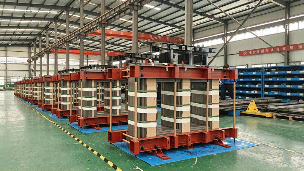
1.3 Core Stacking Process
A fully mitered three-step overlapping joint structure is used.
During the stacking process, workers use a feeler gauge for sampling inspection after each layer is stacked. The gap must not exceed 0.3 mm. After the entire core assembly is completed, a closed-circuit test is performed to measure the core-to-ground insulation resistance and check for interlaminar short circuits.
In one Saudi project, the customer’s third-party inspection engineer brought a 0.02 mm precision feeler gauge and inspected the core joints layer by layer. What was written in the final acceptance report? “The core stacking quality exceeds IEC standard requirements.” That is exactly the result we aim for. Although these details increase manufacturing costs, they can effectively reduce long-term operational risks.
II. Coil
Winding manufacturing directly determines the long-term operating reliability of the transformer. Especially under conditions such as short-circuit impact, electromagnetic vibration, and repeated thermal cycling, winding mechanical strength and insulation margin are the key control factors.
2.1 Conductors and Insulation Materials
The winding conductors use oxygen-free copper conductors or copper foil. Winding conductors and insulation materials are manufactured according to the corresponding IEC material standards. Enamelled wire and paper-covered wire conductors comply with the IEC 60317 series requirements, while solid insulation materials such as insulation paperboard comply with the IEC 60641 series requirements. Insulation thickness is determined based on electric field simulation calculations. The thermal aging performance of the insulation system is evaluated according to IEC 60216, while the electrical withstand level follows the test requirements of the IEC 60076 series.
For renewable energy projects in the Middle East, it is also necessary to consider the thermal-mechanical alternating stress caused by load fluctuations and large day-night temperature differences.
2.2 Winding Method
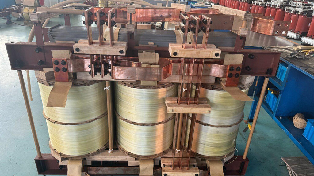
The winding process is divided into two types — layer winding and disc winding.
Small and medium-capacity transformers usually use layer winding, where the conductor is wound layer by layer, similar to winding a coil onto a spool.
Large-capacity and high-voltage transformers typically use disc winding, where individual discs are wound separately and then connected in series.
The advantage of disc winding is that if a problem occurs in one disc, it will not affect the entire phase winding. Disc windings can improve the mechanical strength of the winding and optimize voltage distribution.
2.3 Axial Compression Force Control
During the winding process, axial compression force is a key manufacturing parameter.
If the compression force is too high, it may squeeze and damage the turn-to-turn insulation.
If the compression force is insufficient, during transformer operation, electromagnetic vibration and thermal cycling caused by load changes may cause conductor displacement and friction, resulting in insulation wear and eventually leading to partial discharge failures.
The production process uses a hydraulic constant-pressure compression device, with compression pressure fluctuation controlled within ±5%.
During the winding process, the main control parameters include conductor tension, insulation wrapping, spacer block arrangement, and compression pressure. Visual inspection and dimensional inspection are carried out.
The turn-to-turn impulse withstand voltage test is performed after the complete winding is finished. The dielectric loss test is conducted after winding assembly and vacuum drying are completed.
III. Active Part Drying
Active part drying is a critical process that determines transformer service life.
After the windings and core are assembled, the complete active part is placed into a vacuum drying chamber for vacuum drying treatment.
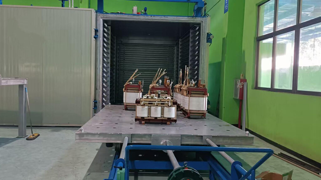
Insulation paper is a type of moisture-absorbing fiber material. The moisture content of the raw material is typically around 6%–8% when it leaves the factory.
If deep drying treatment is not performed before oil filling, the moisture remaining inside the insulation will gradually migrate into the insulating oil, reducing the electrical insulation strength.
More seriously, when the transformer operates under heat, moisture inside the insulation may vaporize and generate internal pressure, which can cause:
- Insulation blistering
- Layer separation and delamination
- Reduced insulation performance
The generated bubbles can also trigger partial discharge and accelerate insulation aging.
Especially for Middle East projects operating under long-term high-temperature conditions, the damaging effects caused by moisture become even more significant.
Therefore, a strict vacuum drying process must be applied to reduce the residual moisture content in solid insulation to a very low level, ensuring the transformer’s long-term operating reliability.
3.2 Drying Process Parameters
IEC 60076-14 provides guidance on transformer insulation drying processes, but the standard does not specify mandatory numerical requirements.
The general industry reference target is that the residual moisture content of solid insulation should be ≤0.5%.
For Middle East projects, our internal factory control target is reduced to ≤0.3%, which is stricter than common industry practice.
The drying process is as follows:
The active part is first heated to 110–115°C, followed by atmospheric pre-drying for 12 hours.
After that, the transformer enters the high vacuum stage, where the vacuum level is reduced to below 50 Pa and maintained for no less than 48 hours.
The complete drying cycle is normally more than 72 hours.
Note: The time is only the minimum process reference. The final drying completion judgment must be based on comprehensive evaluation of:
- Temperature conditions
- Vacuum level
- Moisture release rate
- Dew point variation
Drying completion cannot be determined simply by time alone.
3.3 Moisture Release Monitoring
During the drying process, a condenser is used to collect the extracted moisture.
The amount of released water is monitored every hour and recorded as a drying curve.
When the moisture release rate drops below 5 ml per hour, the drying process is considered to have reached the required level.
Different manufacturers may use different drying curves. The actual drying duration depends on:
- Transformer capacity
- Weight of insulation materials
- Equipment structure
Determining whether drying is complete should not rely only on time. More importantly, engineers need to evaluate:
- Vacuum pressure changes
- Condensed water release trends
- Final insulation moisture indicators
IV. Final Assembly
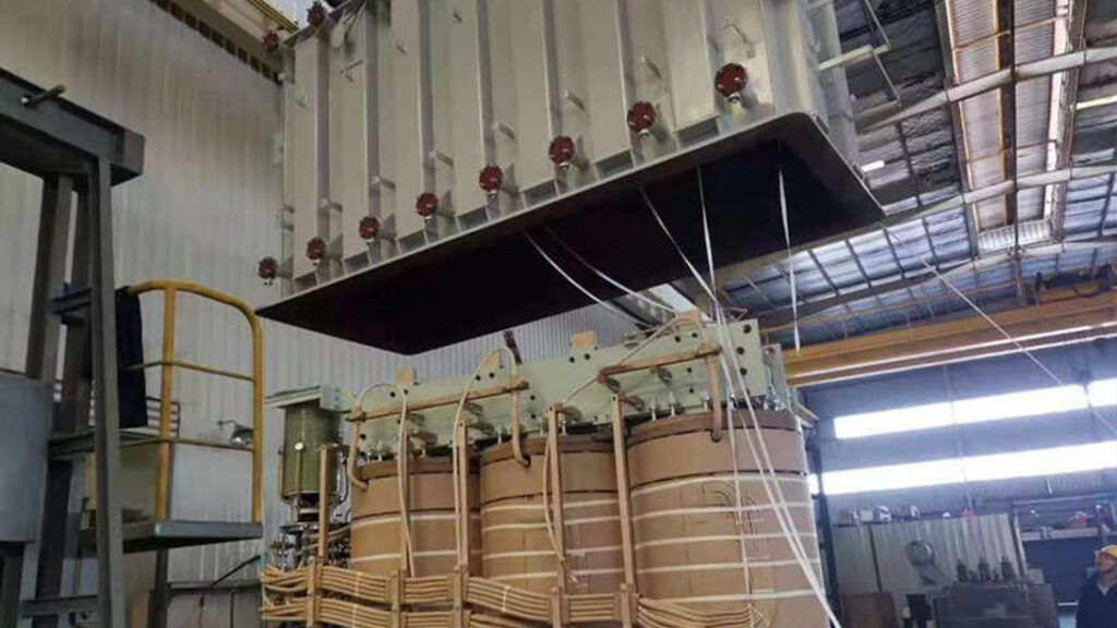
4.1 Hot Assembly and Lifting
After the active part drying process is completed, final assembly is carried out while the transformer is still hot.
Why assemble while hot? Because after drying, the insulation materials are in a dry and expanded state. Once the temperature drops, they may absorb moisture from the surrounding air, which would compromise the previous drying work.
The core and winding assembly are lifted into the transformer tank. The capacity of the overhead crane depends on the equipment weight. Some transformers require only several tons of lifting capacity, while others require dozens of tons.
During the entire process, no collision or mechanical impact is allowed. The clearance between the winding end insulation components and the tank wall must comply with the design drawings, generally controlled within 30–50 mm.
4.2 Lead Connection Welding
The next step is lead connection welding.
Although this process looks simple, it actually requires significant technical experience.
For copper conductor welding, we use medium-frequency induction brazing, with the temperature controlled between 750°C and 850°C.
If the temperature is too low, the welding penetration will be insufficient, resulting in increased contact resistance.
If the temperature is too high, the copper material may undergo annealing, reducing mechanical strength.
After each lead is welded, a micro-ohmmeter is used to measure the contact resistance and compare it with the standard value. If the deviation exceeds 5%, the welding must be redone.
In a Kuwait project, the customer required X-ray inspection records for all welding points. A transformer may have more than twenty welding points of different sizes, and each one was inspected individually.
During the factory acceptance inspection, the customer reviewed the X-ray images and commented:
“Your welding quality control is even more rigorous than pressure pipeline manufacturing.”
V. Oil Filling
Oil filling is the final assembly process before the transformer tank is sealed.
5.1 Oil Treatment
The insulating oil is processed in advance.
Whether it is mineral oil or natural ester, it must first undergo incoming inspection, including:
- Dielectric strength
- Dielectric loss factor
- Moisture content
- Gas content
IEC 60296 and IEC 60422 provide relevant guidance on insulating oil quality requirements and maintenance.
Unqualified oil is never allowed to enter the transformer tank.
The oil filtration system operates continuously, and the oil is circulated under heating and vacuum conditions to gradually remove moisture and dissolved gases.
Oil treatment usually requires 48–72 hours.
Only when:
- Oil breakdown voltage is stable above 70 kV
- Dielectric loss factor is below 0.2%
will the oil filling process begin.
5.2 Vacuum Oil Filling
Oil filling is performed using the vacuum oil filling method.
The transformer tank is evacuated to a vacuum level of below 50 Pa and maintained for at least 8 hours.
Then, the treated oil is pumped into the transformer from the bottom of the tank.
The oil filling speed is critical and must be controlled at no more than 1.5 tons per hour.
If the filling speed is too high, oil flow can generate static electricity, and the issue of oil flow electrification can become extremely dangerous in high-voltage, large-capacity transformers.
5.3 Oil Settling
After the transformer is filled with oil, it is left to settle for 48–72 hours.
This allows small air bubbles inside the oil to gradually rise and escape.
After the settling period, another oil sample is taken for testing and compared with the results before oil filling. All performance indicators must not deteriorate.
VI. Installation of Radiators and Accessories
6.1 Radiator Installation
For corrugated oil tanks, the radiator fins are welded before leaving the factory.
For transformers using panel-type radiators, installation is completed separately.
Before radiator installation, a pressure sealing test is performed.
A pressure of 0.1 MPa is maintained for 12 hours without leakage.
During installation, flange bolts must be tightened in a diagonal sequence.
The tightening torque is controlled using a torque wrench. Single-side tightening is not allowed.
6.2 Accessory Installation and Inspection
External accessories including:
- Bushings
- Tap changers
- Oil level gauges
- Temperature indicators
- Pressure relief devices
- Gas relays
are installed one by one.
Each accessory has corresponding IEC standards.
For example:
- Bushings comply with IEC 60137
- Tap changers comply with IEC 60214
Gas relays are tested for operation performance and sealing according to relevant product standards.
Each accessory is inspected immediately after installation.
After bushing installation:
- Dielectric loss testing
- Capacitance measurement
are performed.
After tap changer installation:
- Operation tests
- Contact resistance measurements
are carried out.
Any component that does not meet the requirements is replaced immediately.
VII. Final Product Testing
Final product testing, also known as Factory Acceptance Test (FAT) in projects, is the most important quality verification stage before transformer delivery.
The IEC 60076 series divides transformer tests into three categories:
- Routine tests
- Type tests
- Special tests
7.1 Routine Tests
Routine tests are performed on every transformer unit.
The test items include:
- No-load loss test
- Load loss test
- Short-circuit impedance test
- No-load current test
- Voltage ratio and vector group test
- Power frequency withstand voltage test
- Induced voltage withstand test
All seven items must be completed without exception.
7.2 Type Tests
Type tests are generally performed on the first unit of a transformer design.
The test items include:
- Temperature rise test
- Lightning impulse test
- Short-circuit withstand capability test
- Sound level measurement
- Switching impulse test
For transformers used in Middle East projects, the first unit is usually sent to an independent third-party laboratory for testing, with the customer present for supervision.
7.3 Special Tests
Special tests are conducted according to project requirements.
Typical items include:
- Partial discharge measurement
- Oil flow electrification measurement
For Middle East projects, partial discharge testing has basically become a standard requirement.
7.4 Actual Test Data
A 20,000kVA/132kV transformer for a Saudi project that was recently completed:
No-load loss:
Design guaranteed value: 16.5 kW
Measured value: 15.3 kW
Load loss (converted value at 75°C):
Design guaranteed value: 85 kW
Measured value: 83.7 kW
Short-circuit impedance:
Design value: 13%
Measured value: 13.12%
Top oil temperature rise:
IEC limit: 60K
Measured value: 41.2K
Winding hot-spot temperature rise:
IEC limit: 78K
Measured value: 53.5K
Partial discharge:
At 1.1 times rated voltage: 18pC
Every parameter has sufficient margin.
During actual manufacturing, we focus not only on meeting the minimum standard requirements but also on creating sufficient quality margin.
VIII. Two Additional Special Tests
8.1 High-Temperature Simulated Load Test
High-temperature simulated load testing.
In a workshop environment with an ambient temperature of not less than 45°C — summer conditions are ideal for this test — the transformer is operated at 1.1 times rated load continuously for 72 hours.
During the entire process, temperature rise at different locations and oil dissolved gas analysis changes are continuously monitored.
After passing this test, we can have higher confidence that the transformer can operate reliably under full load in a 50°C field environment.
8.2 Dust Environment Simulation Test
Dust environment simulation testing.
Inside a sealed test chamber, ISO 12103-1 A2 standard fine dust is blown onto the external surface of the transformer for 2 hours.
After completion, a white cloth is used to wipe the internal surfaces near sealing areas.
No visible dust particles are allowed to be found.
This test is not required by IEC standards. It is an additional internal verification test developed by ourselves.
If a transformer is expected to operate in desert conditions for 25 years, spending two additional days on testing is completely worthwhile.
IX. Frequently Asked Questions
What is the difference between IEC standards and ANSI standards? Which standard do you follow?
The Middle East market mainly follows IEC standards.
Saudi Arabia’s SASO, UAE standards UAE.S, and Qatar standards QCS generally adopt IEC-based requirements.
All our products are designed and manufactured according to IEC 60076 standards.
If customers specifically require ANSI standards, we can also provide ANSI-compliant solutions, but the majority of Middle East projects follow the IEC approach.
How long is the manufacturing lead time?
For transformers below 20MVA, the period from contract signing to shipment readiness is approximately 90–100 days.
Compared with conventional products, the additional time mainly comes from extra desert-specific testing requirements.
For urgent projects, early communication is required. The fastest delivery can be achieved within 75 days.
Where do the materials come from?
According to project requirements, we can use internationally recognized brands or customer-specified supply systems, including imported silicon steel sheets, insulation materials, transformer oil, and high-voltage accessories.
Can customers inspect the manufacturing process?
Customers are always welcome to conduct inspections.
Our factory has a dedicated inspection office with complete communication facilities.
For key manufacturing stages, we provide advance notification.
If customers cannot visit personally, we can provide video monitoring and remote inspection support.
The following stages are strongly recommended for customer supervision:
- Core stacking
- Vacuum drying
- Oil filling
- Final product testing
These are the critical quality control points of transformer manufacturing.
X. Final Remarks
IEC standards are not just certificates displayed on the wall. They are detailed operating requirements verified and controlled through every manufacturing step.
Manufacturing is not about whether a company can achieve a certain standard once. The real challenge is whether it can achieve the same quality level consistently every time.
A transformer operating in a desert environment needs to withstand 25 years of continuous operation.
From the very first step of silicon steel sheet cutting, there can be no compromise.
Zisheng Electric has been continuously involved in projects across the Middle East, Africa, South America, and other regions, providing EPC contractors, project owners, and engineering companies with transformer selection, technical documentation support, and manufacturing coordination services.
Our annual repair rate remains below 0.5%.
We may not always be the lowest-cost supplier, but our reputation is built through every transformer manufactured and delivered.
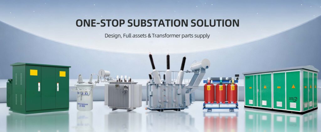
Our product portfolio includes:Oil-Immersed Transformers, Compact Substation, Pad Mounted Transformers, Pole Mounted Transformers and Dry Type Transformers.
Zisheng Electric has obtained 22 utility model patents and 3 software copyrights, is certified under the ISO 9001 Quality Management System, and complies with relevant IEC standards for transformer design and manufacturing.
For projects in different regions, transformer selection requires more than simply considering rated capacity and voltage level.
Our engineering team will assist with technical matching according to IEC requirements and provide an initial response within 24 hours.
About ZISHENG ELECTRICAL
Zisheng are a professional 19+ years manufacturer in producing Oil-Immersed Transformers, Compact Substation, Pad Mounted Transformers, Pole Mounted Transformers and Dry Type Transformers. We own the certificates of ISO/CE/IEC 60076 and TUV Rheinland.
Transformers undergo rigorous FAT and type testing, support voltage/capacity customization. Welcome to consult for Catalog and Product. you can contact us at email [email protected].