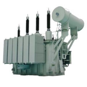
Transformer Cooling Pump Failure: 6 Decisions Before Restoring Industrial Load
A transformer cooling pump failure can leave an industrial plant with two different problems: less cooling than the operator expects, and incomplete evidence about what actually stopped. Zisheng Electric recommends treating the alarm as an operating-state decision first. Identify the affected circuit, establish the cooling that remains available, and apply the transformer-specific response before concentrating on repair.
This guide is for plant electrical managers, maintenance planners and EPC teams preparing the operating package for forced-oil-cooled power transformers. It addresses the decision process around an abnormal cooling state. Switching, isolation, inspection and testing belong to qualified personnel working under the approved site procedure and equipment manuals.
1. Establish what transformer cooling pump failure means on this unit
Start with the nameplate, cooling schematic and approved rating schedule. A transformer using natural oil circulation does not acquire a pump-dependent rating simply because it has cooling fans. Conversely, a forced-oil arrangement may rely on circulation through a particular cooler bank or directed winding path. Losing that path is not equivalent to losing one fan.
A transformer cooling pump failure review must answer a specific operating question: which approved cooling state can this transformer actually maintain now? Record the pump identity, bank arrangement, available auxiliaries and selected control mode. Where the documentation is incomplete, escalate the missing duty information instead of inventing a remaining capacity from the number of running motors.
A 50% loss of pumps does not establish a 50% permissible load. Shared headers, standby arrangements, hydraulic paths and thermal design can produce very different consequences. The approved response may also depend on the load and temperatures immediately before the failure.
2. Separate the command, motor and circulation evidence
A green lamp may represent a start command, a contactor position, motor current or a flow switch. These are different observations. Read the drawing and the actual point description before calling a cooling bank healthy. A command can remain present when the motor supply has failed; a running motor does not by itself prove the required oil circulation.
Reinhausen’s CEDASPE SCFR2 description illustrates the distinction: the device monitors circulating dielectric fluid through a paddle and provides visual and electrical indications. Its published application data are device-specific. They are not universal flow thresholds for every transformer.
Build a short event sequence
Preserve the cooling demand, start command, motor feedback, flow indication, supply condition and temperature trend on a common time basis. Note whether the alarm appeared during a start, after a supply transfer, during steady operation or after maintenance. Also record whether a standby pump started and whether its flow was actually confirmed.
Do not clear the sequence simply to make the alarm screen look normal. If local and remote indications disagree, retain both readings with their timestamps and identify the unresolved signal path. An acknowledged alarm is an administrative state, not evidence of restored circulation.
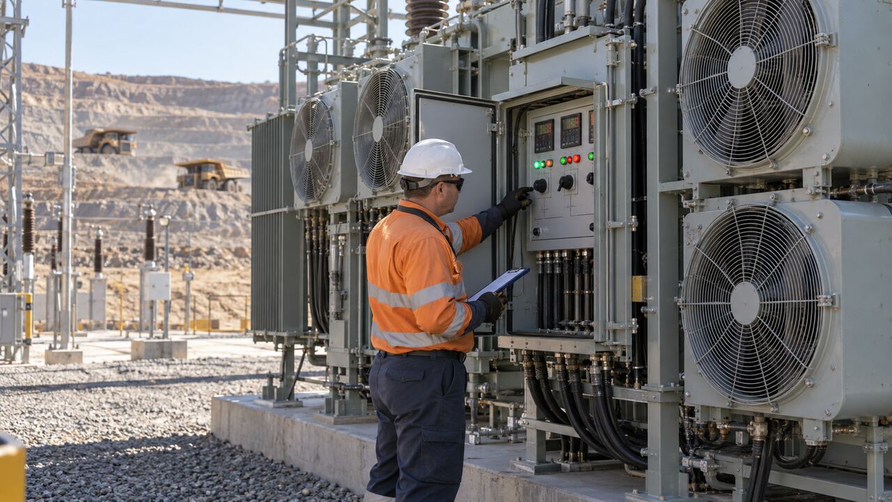
3. Make the operating decision before the repair decision
The operator needs an approved action while diagnosis continues. Use the transformer manufacturer’s loss-of-cooling instructions, the owner’s operating rules and the actual protection scheme. Possible actions include an authorized reduction in demand, controlled load transfer or taking the transformer out of service. Which action applies cannot be settled by a generic online table.
IEC 60076-7:2018 covers loading of mineral-oil-immersed transformers in relation to temperature and thermal ageing. Its scope supports reviewing ambient conditions, loading history and thermal behaviour together. The public scope does not supply a universal emergency allowance after an oil pump stops, and this guide does not reproduce a normative loading calculation.
For an ester-filled or otherwise different insulation system, confirm the applicable loading basis separately. Keep site temperature settings, time delays and trip logic in the controlled operating documents. Do not change them to extend production during the event.
| Observed condition | What remains uncertain | Required operating decision |
|---|---|---|
| No motor feedback and no confirmed flow | Supply, starter, motor or mechanical cause | Apply the approved loss-of-cooling response; establish the available cooling state |
| Motor feedback present, flow indication absent | Actual circulation versus indication fault | Do not credit the affected circuit until the discrepancy is resolved |
| Standby command issued | Whether the standby circuit established circulation | Verify its actual feedback before treating redundancy as restored |
| Local flow indication and remote alarm disagree | Contact, wiring, input mapping or device condition | Record both states and use the approved response for uncertain cooling availability |
| Cooling restored but abnormal temperature trend remains | Residual heat, measurement issue or another problem | Hold the load increase for engineering review |
Do not wait for one dial to settle the question
Top-oil temperature, a simulated winding indication and a direct winding sensor are not interchangeable measurements. The winding temperature indicator interface guide explains why the sensing arrangement and current input matter. Use the actual instrument description when interpreting an event.
Record the direction and rate of change as well as the displayed value. A single comfortable reading immediately after a cooling failure does not prove a stable operating condition. The authorized duty decision should identify who watches the trend, how the operating limit is communicated and what event triggers further action.
4. Investigate the failed circuit without changing the evidence
After the operating state is controlled, prepare a focused investigation. Useful work packages distinguish electrical supply and controls, the pump assembly, the fluid circuit and the monitoring device. That division helps avoid replacing a motor when the event began with a lost auxiliary supply or an incorrectly identified flow contact.
Compare the as-found condition with the approved cooling schematic and the last maintenance record. Record recent work, valve line-up documentation, pump identification and any changes to the control configuration. Establish inspection and test requirements with the relevant equipment specialists; this article does not prescribe opening valves, venting, accessing live circuits or repeatedly restarting a stalled pump.
Account for the plant environment
At a remote mine, the practical constraint may be a delayed replacement motor or a specialist who cannot mobilize that day. At a cement works, dust and restricted maintenance access may complicate cooling work. In a hot outdoor yard, the operating assessment needs the actual ambient conditions rather than an assumed regional maximum.
For the wider design and maintenance context, see the tropical mining transformer cooling guide. The present decision is narrower: establish what failed and which documented duty is available during the repair window.
5. Verify restoration after transformer cooling pump failure
Define the transformer cooling pump failure return checks before completing the repair. The scope should address the identified defect, required fluid-system work, control and protection restoration, and confirmation that the intended cooling circuit responds in the approved operating modes. A motor replacement invoice is not a complete restoration record.
The test record should link the local equipment identity to the control-room indication. If a flow switch, contact or SCADA input was involved, verify the relevant signal path rather than checking only the local display. Any temporary test links, forced inputs or control overrides need recorded removal and independent confirmation under the site’s normal rules.
Then document a supervised observation period under an authorized load condition. Compare the relevant temperatures and cooling indications with the pre-event history where it is comparable. The responsible engineer sets the duration and criteria for this equipment; there is no generic five-minute or one-hour release rule here.
6. Turn the incident into a better purchase and maintenance package
For the next purchase or retrofit, ask for an operating-state schedule that explains each cooling arrangement, its prerequisites, failure indications and owner-approved response. Specify whether standby equipment is installed, how common supply failures are handled, and which proof signals the control room receives. Redundancy that shares an unreviewed failure point can be less useful than its equipment count suggests.
Request a maintainable spare strategy: exact pump and motor identities, electrical supply data, fluid compatibility, mounting interfaces, recommended preservation and supplier support scope. Confirm the engineering review required before accepting an alternative assembly. Similar external dimensions do not establish equivalent hydraulic performance.
Questions to close before raising load
- Has the failed cooling state been identified and the defect addressed?
- Does the restoration record show circulation and the corresponding signal path?
- Have temporary test conditions been removed and normal protection restored?
- Are the observed operating conditions acceptable under the approved duty assessment?
- Who has authorized the load increase and who owns the follow-up inspection?
Transformer cooling pump failure: practical questions
Can the transformer keep supplying the plant?
A transformer cooling pump failure does not establish a standard reduced-load percentage. The decision needs the approved rating available with the remaining cooling, the actual loading and temperature history, and the manufacturer’s instructions. Record the authorized duty and escalation conditions while the defect is being investigated.
What should the RFQ for a replacement pump include?
After a transformer cooling pump failure, provide the original assembly identification, nameplate photographs, supply voltage and frequency, connection and mounting drawings, insulating-fluid details and any available hydraulic duty data. Ask the supplier to identify missing inputs and confirm compatibility in writing. Make the required review of an alternative assembly part of the purchase approval, with supporting technical documents attached.
What belongs in the release record?
Keep the as-found defect, repair scope, equipment identities, control and flow checks, restored protection status and authorized observation conditions together. Include timestamps, unresolved exceptions and the person approving the next operating step. This gives the incoming shift and maintenance planner a usable record of what was demonstrated and what remains to be checked.
Zisheng Electric can review cooling and monitoring requirements for a 110kV or 115kV power transformer or a 132kV or 138kV power transformer. For a transformer cooling pump failure review, provide the nameplate, cooling schematic, pump data, alarm sequence, load history, temperature trends, site conditions and maintenance findings. Our engineering team will review the requirements and respond to project inquiries within 24 hours.
About ZISHENG ELECTRICAL
Zisheng are a professional 19+ years manufacturer in producing Oil-Immersed Transformers, Compact Substation, Pad Mounted Transformers, Pole Mounted Transformers and Dry Type Transformers. We own the certificates of ISO/CE/IEC 60076 and TUV Rheinland.
Transformers undergo rigorous FAT and type testing, support voltage/capacity customization. Welcome to consult for Catalog and Product. you can contact us at email [email protected].