
Transformer Earthing Switch Interlocks: Colombia EPC Commissioning Checks
Transformer earthing switch interlock checks matter most when an EPC team is proving the approved switching sequence before a transformer bay is handed to operations. Zisheng Electric recommends treating the interlock as one engineered layer in the switching system. It does not replace isolation, a permit, testing for absence of voltage, or the owner’s approved procedure.
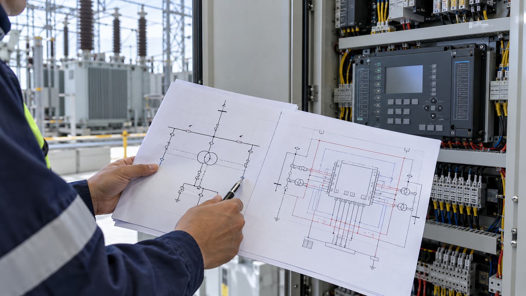
Earthing switch interlock checks: define the equipment boundary
Start from the approved single-line diagram, bay layout, control schematic and operating sequence. Confirm the exact disconnector, earthing switch, circuit breaker, access door and key-exchange points included in the scheme. A drawing may show an interlock contact without making clear which equipment vendor supplies the mechanism, wiring or local indication. Resolve those boundaries before commissioning rather than during a live switching window. A useful earthing switch interlock review starts with a cause-and-effect matrix that assigns the device, control contact, indication and witness evidence to a named supplier.
IEC 62271-102:2022 covers AC disconnectors and earthing switches for indoor and outdoor installations above 1 kV, for service frequencies up to and including 60 Hz. Its scope is useful when defining equipment requirements, but it does not make a particular site sequence universal. The project specification, equipment ratings, manufacturer instructions and applicable Colombian owner or utility rules remain controlling.
Five checks for a controlled commissioning window
1. Walk the approved sequence in both directions
List the permitted and blocked operations for each relevant equipment state. The sequence should identify when the circuit breaker is open, when the disconnector may move, when the earthing switch may close, and what conditions must be satisfied before access is allowed. Check the reverse sequence for restoration. Do not infer the sequence from handle labels alone; compare the operating diagram with the approved switching instruction.
2. Inspect mechanical and trapped-key interfaces
With the bay in the approved de-energized test condition, check that mechanical interlocks engage at the intended positions and that a trapped-key exchange cannot be completed out of sequence. Confirm the key names, custody points and key-return logic against the project schedule. If a door or shutter interlock is included, verify the actual mechanism and its permitted states. A key that can be removed at an unexpected position is a discrepancy to resolve, not a reason to force the mechanism. The earthing switch interlock should be tested against the approved sequence, not judged by key movement alone.
3. Prove electrical interlocks and auxiliary contacts
Trace each electrical permissive from the initiating device through terminal blocks to the receiving coil, relay or control logic. Verify auxiliary-contact identity, normally open or normally closed convention, wiring continuity and the intended fail state against the approved schematic. Separate an interlock that blocks an operating command from an alarm that only reports a position. A correct local indication does not prove the remote logic uses the same contact. For each earthing switch interlock permissive, retain the terminal and contact references used during the check.
4. Compare local position, control-room indication and event logs
At each agreed test state, record the mechanical position flag, local mimic, control-room indication and relevant input status. Resolve any mismatch between a device position and SCADA before the test proceeds. Agree how timestamps are recorded and who witnesses each step. If communications or auxiliary supply are lost, document whether the design blocks operation, retains the last indication or raises an alarm; use the device-specific logic description rather than assuming a universal response.
5. Test the failure response and restore the initial condition
Use only the approved test method, equipment and permit. Demonstrate the intended block for the defined test points without defeating a safety function or creating an energized test condition. Record test configuration, simulated inputs, observed outputs, witness, open findings and restoration checks. Remove temporary links and test leads under the site procedure, then independently confirm the final switch positions and indication before releasing the bay.
What a useful test record should show
| Record item | Evidence to retain |
|---|---|
| Document basis | Approved sequence, schematic revision and equipment identifiers |
| Mechanical checks | Permitted positions, key exchange and any observed interference |
| Electrical checks | Contact state, terminal references, permissive or block response |
| Indication | Local and remote state, alarm text and time reference |
| Closeout | Discrepancy disposition, temporary-link removal and approved final state |
When a test step does not behave as expected
Stop at the defined hold point and preserve the test state. Record the actual device position, control indication, input status and the exact command attempted; then compare them with the approved interlock matrix and current schematic revision. Do not bridge a contact or force a key mechanism simply to complete the witness sheet. The responsible design authority and equipment supplier should agree whether the finding is a wiring discrepancy, a drawing mismatch, a device adjustment issue or an expected design response.
Before repeating a test, document the approved corrective action and the boundary of the retest. Where a software or wiring change affects more than one operating state, review the other affected permissives as well. Close temporary links and test leads through the site’s control process, and attach the revised drawing or disposition to the commissioning record. A concise traceable record helps the operations team distinguish an accepted design feature from an unresolved exception.
Colombia EPC handover: close the interface gaps
For a Colombia project, the local value is in the interface package. The earthing switch interlock handover should include: Spanish operating labels where required by the owner, consistent equipment tags, a controlled key schedule, witness points and a clear responsibility matrix for the switchgear, transformer and control-system suppliers. Confirm the project’s applicable utility and site requirements instead of borrowing a sequence or voltage assumption from another country or facility.
For adjacent transformer protection review, see the site’s transformer fault-diagnosis guide. For a transformer bay supply scope, the 110/115 kV power transformer range is a product reference; the actual bay arrangement and switching devices must follow the project drawings.
Before accepting the bay, ask the EPC contractor and suppliers for the approved switching narrative, interlock matrix, cause-and-effect schedule, contact list, test procedure, signed results and outstanding-action register. Zisheng Electric can review transformer interface requirements during technical clarification. Share the single-line diagram, transformer rating and required control points to request an engineering review.
About ZISHENG ELECTRICAL
Zisheng are a professional 19+ years manufacturer in producing Oil-Immersed Transformers, Compact Substation, Pad Mounted Transformers, Pole Mounted Transformers and Dry Type Transformers. We own the certificates of ISO/CE/IEC 60076 and TUV Rheinland.
Transformers undergo rigorous FAT and type testing, support voltage/capacity customization. Welcome to consult for Catalog and Product. you can contact us at email [email protected].