Kenya Irrigation Transformer Guide for Water Projects: Pump Starting and Long Feeders
A Kenya irrigation transformer cannot be selected from connected kilowatts alone. A pump may sit idle for hours and then demand several times its running current during acceleration. A remote booster station can be supplied through a long medium-voltage feeder, while the treatment plant adds chemical dosing, aeration, lighting, controls, and standby generation. At Zisheng Electric, we review this operating sequence before recommending a rating. Nameplate kVA is only the starting point; feeder impedance, motor-starting method, seasonal duty, ambient conditions, protection, and the expansion plan determine whether the station will accelerate its pumps without nuisance trips or an unacceptable voltage dip.

Kenya Grid Conditions That Affect Irrigation Transformer Selection
Kenya operates on a 50 Hz power system, with 11 kV and 33 kV commonly used in distribution networks. For irrigation and water projects, transformer selection should therefore consider not only rated capacity, but also feeder length, source strength, motor starting current, and voltage variation.
Remote pumping stations are often connected through long feeders, which can increase voltage drop during motor starting. The transformer impedance, tap range, and starting method should be checked together with the upstream network.
Site altitude and environmental conditions also vary across Kenya. Actual altitude, ambient temperature, dust, humidity, and installation conditions should be confirmed before finalizing the transformer design.
How to Specify a Kenya Irrigation Transformer for Variable Pump Loads
Many distribution-transformer quotations begin with a connected-load total and a general diversity factor. That method can work for buildings with numerous small loads. It is risky for pumping systems because one motor may dominate the entire transformer. A 315 kW or 500 kW pump starting across the line can pull a current several times its rated value. Even when a soft starter or variable-frequency drive is used, the starting current, acceleration time, transformer impedance, cable length, and source strength must be considered together.
The practical question is not simply whether the transformer can carry the running current. The engineering team must confirm that bus voltage remains high enough for the motor to accelerate, that contactors and control power do not drop out, and that the upstream protection does not interpret the start as a fault. The same review should include any simultaneous pumps, duty-and-standby philosophy, and automatic restart sequence after a supply interruption.
Irrigation and water projects in Kenya may also place pumping stations a considerable distance from the main substation or utility connection point. Long feeders add resistance and reactance before the transformer, reducing the fault level and increasing voltage drop. A weak source may help limit short-circuit current, but it makes large-motor starting more difficult. The transformer must therefore be selected as part of the complete source-feeder-transformer-motor system.
Build the Load Schedule Around Operating Modes
Separate Running Load from Starting Duty
A useful load schedule has at least four columns beyond rated power: operating mode, expected simultaneous load, starting method, and starting sequence. It should distinguish normal irrigation, peak irrigation, flushing, maintenance, emergency supply, and future expansion. If a project has three pumps arranged as two duty plus one standby, procurement documents must state whether the standby unit can start before the failed motor is isolated. That detail changes the worst-case kVA demand.
Motor efficiency and power factor should come from the selected motor data rather than a generic assumption. The transformer supplies apparent power, not only mechanical kilowatts. Auxiliary loads such as ventilation, lighting, crane sockets, battery chargers, telemetry, and workshop equipment also remain present during pump starting. Leaving them out can produce a design that works in a spreadsheet but fails during commissioning.
| Input | Why It Matters | Procurement Check |
| Largest motor kW and full-load current | Sets the dominant running and starting demand | Use the approved motor datasheet, not an early estimate |
| Starting method and current limit | Determines voltage dip and transformer short-duration duty | Confirm DOL, star-delta, soft starter, or VFD settings |
| Acceleration time | Long acceleration extends thermal and voltage stress | Check pump inertia, head, and valve position |
| Simultaneous operating pumps | Defines normal and peak kVA | Review duty, standby, flushing, and emergency modes |
| Feeder length and conductor data | Affects source impedance and available motor voltage | Include upstream line, cable, and busbar impedance |
| Future expansion | Changes loading, protection, and spare feeder requirements | State the expansion stage and expected implementation date |
Check Motor Starting Against the Complete Network
Voltage Dip Is a System Result
The voltage dip at a motor terminal depends on the upstream grid, medium-voltage feeder, transformer impedance, low-voltage cable, motor characteristics, and starting device. Increasing transformer kVA can reduce transformer voltage drop, but it may also increase prospective short-circuit current. Specifying an unusually low impedance for the same reason can create a switchgear-duty problem. The decision must close both sides of the calculation.
For early comparison, engineers can model the transformer as an impedance on its rated base and add the upstream network impedance. The final study should use the project single-line diagram and manufacturer data for motors and starters. It should test the weakest supply condition, the maximum planned feeder length, and the most demanding permissible starting sequence. A statement such as “motor starting shall be acceptable” is not an engineering criterion. The purchase specification should define the minimum retained voltage at relevant buses or require the EPC electrical study to establish it.
Use Starting Technology Deliberately
Direct-on-line starting is simple and robust, but its current can be difficult for a remote transformer. Star-delta starting reduces current but also reduces starting torque and may not suit a loaded pump. A soft starter can control current and mechanical shock, although the current limit must still allow acceleration. A VFD offers speed control and can improve process efficiency, but it introduces harmonics, switching effects, and additional cooling requirements in electrical rooms.
If a VFD supplies a large share of transformer load, provide the drive topology, harmonic spectrum or expected total harmonic distortion, switching arrangement, and any filters. The transformer designer may need to review additional stray losses and temperature rise. The neutral and earthing arrangement should also be coordinated with drive and control-system requirements.

Select Rating, Impedance, and Cooling as One Package
A transformer for irrigation pump should not be oversized by stacking several unrelated safety factors. Excessive oversizing raises purchase cost, can reduce operating efficiency at light load, and may increase prospective fault current. A better approach is to calculate the maximum continuous kVA for each operating mode, apply one project-agreed loading margin, and then test the selected rating against starting duty, ambient temperature, harmonics, transformer losses, and the confirmed expansion stage.
Transformer impedance is equally important. Lower impedance supports motor voltage but raises fault current. Higher impedance limits fault current but increases voltage drop. If two transformers may operate in parallel, their ratio, vector group, tapping arrangement, and percentage impedance must be compatible. The project team should state whether parallel operation is normal, temporary, or prohibited.
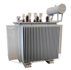
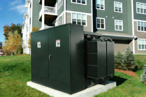
For outdoor pump stations, a liquid-immersed unit is often practical because it handles continuous load well and can be installed close to the load centre. A buyer considering a typical distribution rating can review the published 400 kVA oil-immersed transformer configuration as a reference, while larger packaged stations may use a 750 kVA three-phase pad-mounted transformer. The final selection still depends on voltage, vector group, impedance, losses, enclosure, and site conditions.
| Design Decision | Risk if Under-Specified | Recommended Document |
| Rated kVA | Overheating, poor starting, or unnecessary oversizing | Operating-mode load schedule |
| Percentage impedance | Excessive fault current or unacceptable voltage dip | Short-circuit and motor-starting study |
| Cooling method | Loss of rating in high ambient or restricted airflow | Site-condition and temperature schedule |
| Tap range | Insufficient correction for network voltage variation | Utility voltage limits and load-flow study |
| Neutral arrangement | Protection malfunction or unsafe earth-fault behaviour | Earthing and protection philosophy |
| Enclosure and corrosion system | Moisture, dust, or corrosion damage | Environmental data sheet and coating specification |
Account for Long Feeders and Seasonal Operation
Water infrastructure often expands in stages. The first phase may operate one pump, while later phases add reservoirs, booster stations, or additional irrigation blocks. The transformer should be checked at both ends of that timeline. A large future-ready unit may run lightly loaded for years; two smaller units or a modular substation may provide better efficiency and redundancy. The economic comparison should include transformer losses, switchgear, civil works, maintenance access, spare strategy, and the cost of an outage.
Seasonal duty does not remove the need for thermal review. Repeated high-load periods followed by low load create a different ageing profile from steady operation. Daily ambient temperature, enclosure ventilation, solar exposure, and harmonic losses influence hot-spot temperature. IEC 60076-2:2011 covers temperature-rise limits and test methods for liquid-immersed transformers, while IEC 60076-7:2018 provides guidance on loading and thermal ageing. The project specification should identify the required standard editions and any site-specific ambient conditions rather than copying a generic temperature schedule.
Tap selection deserves attention on long feeders. An off-circuit tap changer can correct a known, stable voltage difference, but it cannot follow daily network variation while energized. An on-load tap changer may be justified for a major substation, though it adds cost, controls, maintenance, and protection interfaces. The load-flow study should establish the required range and normal operating tap before procurement.

Environmental and Installation Details That Affect Reliability
Site questionnaires should record maximum and minimum ambient temperature, altitude, humidity, dust, flooding risk, corrosion category, seismic requirement if applicable, and access for transport and maintenance. A pump station near an open channel needs drainage and plinth elevation review. Cable boxes and marshalling terminals should face the planned cable routes, not whichever side is easiest for the factory drawing.
Altitude affects dielectric clearances and cooling performance. If a station is materially above the standard service altitude assumed by the project standard, the transformer and associated switchgear need coordinated correction. The EPC contractor should provide the actual site elevation for each station because a single water scheme may cross significantly different terrain.
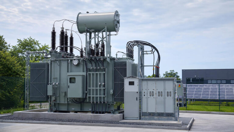
For a packaged installation, verify transformer heat rejection, ventilation paths, internal arc requirements for switchgear, fire separation, and safe working clearances. A compact footprint is useful only if technicians can reach bushings, protection devices, tap-changer access points, cable terminations, and lifting points. The general comparison in our oil-immersed versus dry-type transformer selection guide can help the project team decide which construction is appropriate for outdoor stations, treatment buildings, and occupied areas.

Protection, Earthing, and Fault-Level Coordination
A weak rural feeder may produce relatively low fault current at the remote station. Protection settings must still detect and clear faults within the required time. At the same time, the transformer inrush current and motor starting current must not cause nuisance operation. The coordination study should include upstream utility protection, transformer primary protection, low-voltage main breaker, motor protection, earth-fault elements, and any generator contribution.
For a transformer selection for water projects, short-circuit withstand must be coordinated with both the weakest feeder condition and the maximum future fault level. IEC 60076-5:2006 addresses a transformer’s ability to withstand the effects of external short circuits, including thermal capability and verification of dynamic effects. Procurement teams should not treat a measured impedance value as complete evidence of withstand. For critical equipment, request the agreed design calculations or evidence from a validated design family together with the routine test reports.
The neutral-earthing method must be stated explicitly. It affects transformer winding connection, cable insulation, earth-fault current, protection sensitivity, and generator interface. If standby generators can energize the low-voltage bus, the changeover arrangement must prevent unintended parallel operation unless the equipment and protection are designed for it.
Define the FAT Around the Project Risks
A routine FAT should verify ratio, polarity and phase displacement, winding resistance, short-circuit impedance and load loss, no-load loss and current, dielectric tests, and the operation of accessories required by the purchase specification. The exact test programme must follow the agreed standard and contract. For a pump project, FAT should also confirm terminal orientation, cable-box dimensions, control voltage, alarm and trip contacts, protection-device settings supplied by the manufacturer, nameplate data, tap positions, and completeness of loose accessories.
The purchaser should compare measured impedance with the value used in motor-starting and fault studies. Loss figures should be checked against guaranteed values because water infrastructure can operate for many hours each year. A small difference in purchase price may be less important than lifetime energy cost. If the project uses a higher-voltage intake substation, the available 35 kV and 46 kV power transformer range provides a useful reference for the information that must be fixed before design review.

A Practical Procurement Sequence
Issue the single-line diagram, load schedule, motor datasheets, starting philosophy, site conditions, and expansion plan with the request for quotation. Ask bidders to state guaranteed losses, impedance, temperature rise, tap range, cooling method, sound level if relevant, dimensions, mass, accessory list, deviation schedule, drawing programme, FAT plan, and delivery scope. Technical comparison should be made on aligned assumptions. A lower-priced offer is not truly comparable if it excludes cable boxes, surge arresters, monitoring devices, commissioning support, or the required test documentation.
Before releasing manufacturing, close the transformer datasheet, general arrangement drawing, terminal plan, cable-box drawing, protection schematic, bill of materials, nameplate, and document register. Use the approved impedance in the updated fault and motor-starting studies. During FAT, record the final measured values as the installation baseline. After delivery, inspect impact indicators if specified, oil level, pressure, seals, accessories, paint, and transport damage before energization.
Final Check Before Ordering a Kenya Irrigation Transformer
A reliable pump station transformer is the result of coordinated decisions: pump starting, feeder voltage drop, fault level, ambient conditions, seasonal operation, earthing, protection, and future expansion. Treating those items separately tends to move risk from one part of the project to another.
Zisheng Electric supplies Oil-Immersed Transformers, Pad Mounted Transformers, Pole Mounted Transformers , Dry Type Transformers,and related power distribution equipment. We can provide technical matching based on project capacity, voltage level, environmental conditions, and technical specifications, with an initial response to inquiries within 24 hours. A single-line diagram, motor list, starting method, feeder data, and site-condition schedule are enough for our engineers to begin the preliminary review.
About ZISHENG ELECTRICAL
Zisheng are a professional 19+ years manufacturer in producing Oil-Immersed Transformers, Compact Substation, Pad Mounted Transformers, Pole Mounted Transformers and Dry Type Transformers. We own the certificates of ISO/CE/IEC 60076 and TUV Rheinland.
Transformers undergo rigorous FAT and type testing, support voltage/capacity customization. Welcome to consult for Catalog and Product. you can contact us at email [email protected].