
Transformer Surge Arrester Coordination for African Distribution Projects: Ratings, Placement and Handover
Zisheng Electric treats transformer surge arrester coordination as a package interface that begins before the transformer is ordered. A purchase schedule can name an arrester and a transformer separately, yet leave the connection lead, insulation level, earthing route and acceptance evidence unresolved. Those omissions become expensive when a distribution transformer reaches a constrained site and the EPC contractor discovers that the arrester can only be mounted with a long, exposed lead.
This guide is written for African distribution projects, but it does not assume a common national voltage, lightning exposure, utility rule or earthing design. Those values belong to the actual network and project specification. The engineering objective is to make the arrester selection, location and installation evidence match the transformer terminals and the site environment before procurement release.
Define transformer surge arrester coordination as a system task
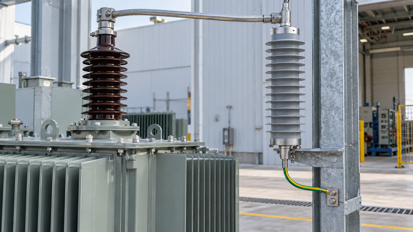
An arrester is a voltage-limiting device. Its nameplate alone does not demonstrate that a transformer is protected. The designer must compare the expected overvoltage duty with the arrester’s protective characteristics and the insulation withstand of the equipment it is intended to protect. The connection between arrester and transformer contributes voltage during a fast surge, so the installed arrangement matters as well as the catalogue curve.
IEC 60099-4 covers metal-oxide surge arresters without gaps for AC systems, while IEC 60071-1 addresses insulation coordination principles. These are different parts of the decision: the first helps specify the arrester, and the second frames the insulation-coordination study. The applicable editions and any utility additions should be identified in the contract. Neither standard supplies a universal arrester rating for all distribution sites.
Start with the single-line diagram and the transformer data sheet. Identify the highest system voltage, earthing arrangement, temporary overvoltage assumptions, transformer insulation levels, line or cable entry, switching scheme and the location of every terminal to be protected. Record who owns the coordination study and who signs off any change to the as-built layout.
Separate electrical selection from physical placement
Electrical selection addresses continuous operating voltage, temporary overvoltage withstand, nominal discharge current, energy and charge duty, residual voltage and environmental classification. Placement addresses conductor length, bends, cable termination, mechanical support, creepage, access and a low-impedance path to the local earth system. An acceptable catalogue selection can perform poorly if the installation creates avoidable lead voltage.
For a compact distribution kiosk or pad-mounted arrangement, check whether the protective device belongs inside the enclosure, at the cable entrance or on the incoming structure. That choice depends on the approved product design, clearances, access and utility interface. A remote pole-mounted arrester may protect an overhead line segment without automatically giving the transformer terminal the same protection as a correctly installed terminal arrester.
Build the procurement decision table
Use the table below as an interface register. It is deliberately free of invented local grid values; enter the approved site data and the candidate device characteristics before issuing the purchase order.
| Decision | Project evidence needed | Why it changes the choice | Release action |
|---|---|---|---|
| Network and earthing | Highest voltage, neutral arrangement and fault-clearing assumptions | Continuous and temporary overvoltage duty depend on the actual system | Confirm rating against an approved study |
| Transformer insulation | Insulation levels at the protected terminals and applicable test documents | The protective margin must include installation effects | Review arrester and transformer as one package |
| Exposure and location | Overhead or cable entry, switching configuration and surge study | Surge path and protected equipment location affect placement | Freeze a marked-up arrangement drawing |
| Connection lead | Route, length, conductor and earthing detail | Fast-current voltage drop can add to terminal stress | Inspect the as-built path before energization |
| Environment | Pollution, rain, altitude, temperature, corrosion and enclosure conditions | Housing and mounting must suit the installation | Approve environmental class and hardware |
| Maintenance | Access, disconnector indication, spares and replacement procedure | Inspection and fault response need safe access | Include items in the handover pack |
The table is useful at a bid review because it distinguishes a missing study input from a simple material substitution. If the utility fault-clearing assumptions are unknown, the team cannot close the temporary-overvoltage check by choosing a familiar stock item. If the electrical study is complete but the enclosure drawing lacks mounting space, the issue moves to mechanical design and vendor coordination.
Check arrester voltage and temporary overvoltage duty
The maximum continuous operating voltage must be compatible with the highest voltage that can remain across the arrester in normal operation. Temporary overvoltages can last long enough to stress a metal-oxide arrester thermally. Their magnitude and duration depend on system earthing, faults, load rejection and switching. Ask the system designer for the relevant cases and compare them with the manufacturer’s capability curve; do not assume that a catalogue voltage label is sufficient.
A margin that appears generous in one direction can weaken protection in another. A higher rating may withstand temporary overvoltage more comfortably but can also change the residual voltage that the transformer sees during a surge. A lower rating may improve protection at the terminal while failing the system’s temporary-overvoltage duty. The coordinated choice must satisfy both constraints with the actual candidate product data.
For networks with multiple voltage levels or future uprating, record which operating configuration the selection covers. An EPC project may install a transformer before a new feeder is energized, or an owner may alter the earthing scheme later. The handover record should identify the assumptions that would trigger a fresh study. This is especially useful for distributors holding standardized stock for several customers.
Allow for the installed protective level

The manufacturer provides characteristic protective levels under specified test conditions. At the transformer terminal, voltage can be higher because current flows through the connection leads and the local earth path. Lead inductance is particularly relevant to a steep front. Keep the high-voltage connection and return path direct within the approved clearances, and let the coordination study evaluate the actual layout where the exposure warrants it.
Review each phase and each terminal that requires protection. The drawing should show conductor entry, cable box or bushing, arrester mounting point, support bracket, earth bond and available service clearance. A generic arrow labelled “surge arrester” on a single-line diagram does not settle those interfaces. A plan and elevation help the transformer vendor, cable contractor and civil team see different conflicts before fabrication.
Confirm that the arrester arrangement is compatible with the transformer design. On an outdoor unit, support and mechanical loads should not be imposed on a bushing unless that arrangement is explicitly approved. Inside an enclosure, allow for safe access, ventilation, drainage and the manufacturer’s required clearance. See the site’s transformer voltage regulation guide for a separate example of why network assumptions should be fixed before transformer selection.
Connect the African site environment to hardware decisions
“African project” is not an environmental specification. An inland industrial yard, a coastal feeder, a high-altitude mining site and a densely built utility kiosk present different insulation, corrosion, transport and maintenance constraints. Obtain the site’s coordinates, elevation, ambient range, pollution description, rainfall and access conditions. Confirm whether the installation is indoor, outdoor, fenced or enclosed. Leave any unverified country-wide generalization out of the specification.
Salt contamination, industrial dust and humidity can affect external insulation and hardware selection. Specify the housing and exposed metalwork for the agreed pollution and corrosion environment, using the utility’s actual requirements where applicable. At altitude, external insulation and clearance may need an engineering review based on the project elevation. Transport and handling requirements should cover fragile housings and spare arresters, especially when a project has several road or warehouse handoffs.
For a coastal procurement scenario, the coastal Ghana transformer procurement article provides a related discussion of project environment; its local assumptions must still be checked against the current site. A distributor should retain an approved drawing and bill of materials for each variation rather than treating all “outdoor arresters” as interchangeable.
Assign interfaces across transformer, EPC and utility teams
Decide who supplies the arrester, mounting kit, phase leads, earth conductor, cable termination and spare unit. If the transformer supplier provides the bracket but the EPC team provides the arrester, freeze hole pattern, mass, connection orientation and terminal interface before the transformer enters manufacture. If the utility provides a line-side device, the EPC team should still confirm whether the transformer terminal requires additional protection under the approved study.
Include a responsibility matrix in the purchase order. The transformer supplier can provide insulation and terminal data; the system designer owns overvoltage cases; the arrester manufacturer supplies characteristic and temporary-overvoltage data; the installer verifies the as-built route; and the commissioning authority closes the test and inspection record. Each party needs the same drawing revision. A late change from overhead conductor to underground cable should trigger an interface review rather than a silent field substitution.
For distribution transformers, product geometry matters. Compare the approved arrester arrangement with the 750 kVA three-phase pad-mounted transformer and 250 kVA single-phase pad-mounted transformer product information as starting points for enclosure and cable-entry discussions. Actual ratings, accessories and suitability require the project data sheet and manufacturer confirmation.
Plan FAT, delivery and site acceptance evidence
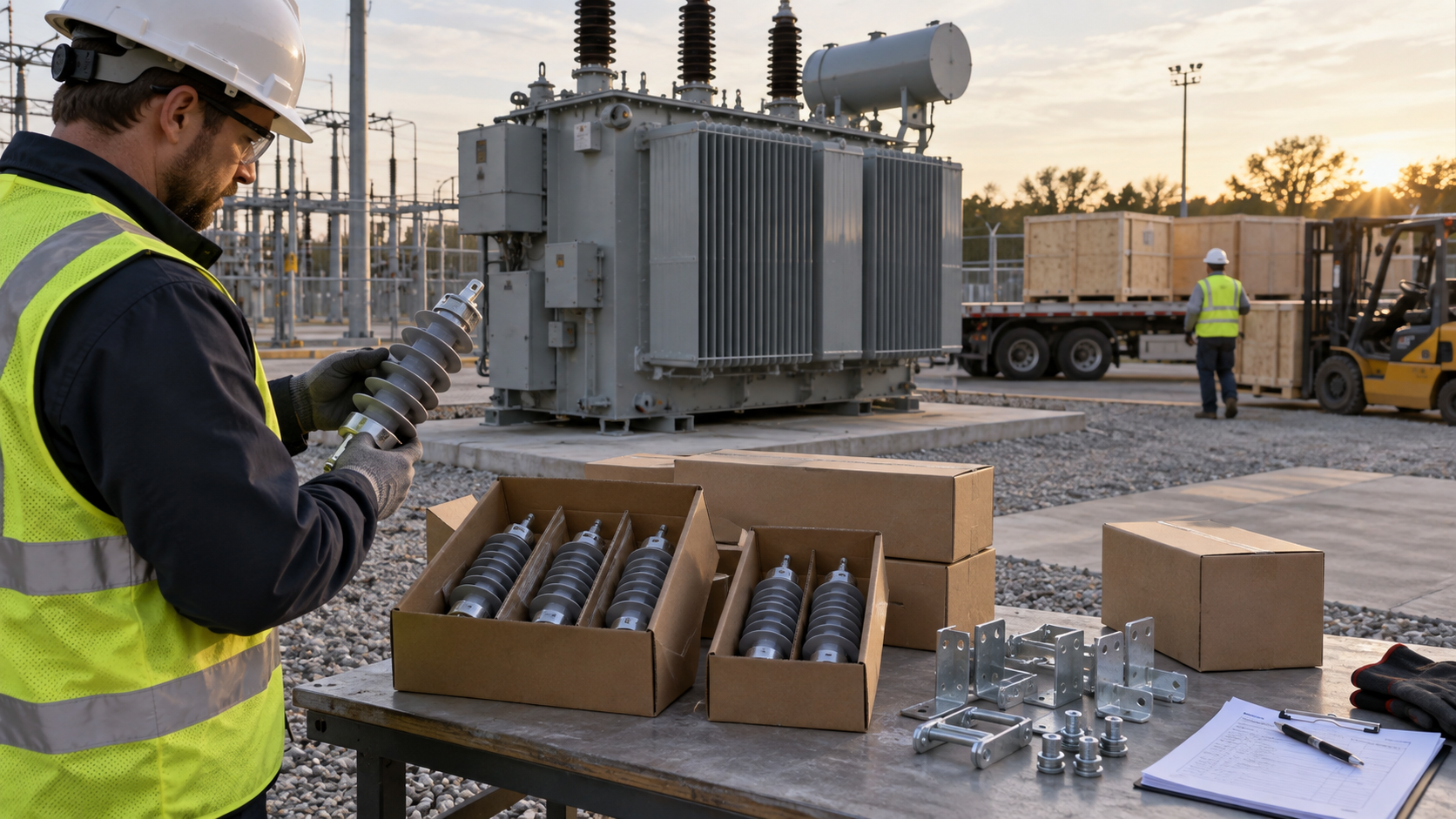
At factory review, compare the bill of materials with the approved arrester type and quantity. Verify the bracket location and connection hardware, inspect insulation and nameplate information, and retain the manufacturer’s test and conformity documentation required by the contract. Do not call a visual check an insulation-coordination test. The design study and equipment documentation establish selection; the factory check confirms that the correct hardware is supplied and fitted.
Before packing, protect housings and terminals against transport damage. List loose parts by transformer serial number and package identifier. At receipt, check the item identity, cracking, chipped housing, moisture damage, missing bolts and preservation instructions. A damaged arrester should be assessed under the manufacturer’s procedure before installation. Storage and replacement logistics matter for remote sites where a missing accessory can hold up energization.
At site, compare the installation with the approved arrangement and earth drawing. Inspect phase connection, fastening, lead routing, bond continuity, clearances, disconnector orientation if fitted, identification and access. A continuity check does not prove a protective margin; it confirms a part of the installed path. Record photographs and the as-left configuration. The EPC team should close deviations with the designer and owner rather than re-routing a lead around an obstruction without a study review.
Commissioning records should link the arrester schedule to the transformer serial number and the feeder or bay. Include relevant design calculations, product data, inspection sheets, earth test references and any deferred punch items. The rural electrification transformer selection guide is a related procurement reference when feeder topology and end-point service affect the package design.
Before the owner accepts the package, ask an engineer who was not responsible for the initial selection to trace one phase from incoming conductor through the arrester connection, transformer terminal and local earth bond on the final drawings. Repeat the walkdown on site. This simple independent review often reveals a drawing revision mismatch, missing termination hardware or a connection that became longer after another contractor installed cable supports. Record the discrepancy, its design consequence and the person authorized to close it. A signed checklist should follow the actual installation, not merely the procurement drawing.
Request a transformer surge arrester coordination review
Transformer surge arrester coordination should be decided while the terminal arrangement, cable entry and earthing design can still be changed. Zisheng Electric can review distribution transformer configurations and the associated accessory interfaces against your approved study. Send drawings, data sheets, load lists, technical specifications, single-line diagrams, grid parameters, environmental conditions and installation-site conditions. Add the insulation levels, fault-clearing assumptions, surge exposure, candidate arrester data, mounting layout and utility interface requirements. Our engineering team will review the requirements and respond to project inquiries within 24 hours.
About ZISHENG ELECTRICAL
Zisheng are a professional 19+ years manufacturer in producing Oil-Immersed Transformers, Compact Substation, Pad Mounted Transformers, Pole Mounted Transformers and Dry Type Transformers. We own the certificates of ISO/CE/IEC 60076 and TUV Rheinland.
Transformers undergo rigorous FAT and type testing, support voltage/capacity customization. Welcome to consult for Catalog and Product. you can contact us at email [email protected].
