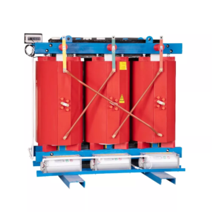
Dry Type Transformer Room Ventilation: Calculate Airflow from Losses
Transformer room ventilation should be sized from the heat released into the room, the permitted air-temperature rise and the actual air density. Transformer kVA alone is not a ventilation calculation. Zisheng Electric recommends agreeing the equipment loss data and room conditions before the ventilation contractor selects fans or the building team fixes louver openings.
This engineering guide develops a hypothetical dry-type transformer room calculation. It is intended for industrial project engineers and procurement teams coordinating electrical and building services. The example is not a completed project, measured performance or an approved design. It demonstrates the decisions needed for projects in Central Asia and Latin America while leaving national codes, utility conditions and equipment limits to project verification.

Start with the heat that enters the room
Transformer output is useful electrical power delivered to the load; it is not all converted into room heat. The heat contribution is mainly the transformer’s losses. No-load loss is present while the unit is energized at the relevant voltage and frequency. Load loss depends on current and the winding’s operating conditions. Obtain both from the offered equipment’s guaranteed data, including reference temperature and the basis of the guarantee.
For an initial estimate at a fixed reference basis, transformer losses can be approximated as P0 + x²Pk. Here P0 is no-load loss in kilowatts, Pk is the loss at rated current and the stated reference conditions, and x is the operating current divided by rated current. This is a screening approximation. Actual temperature, harmonic currents and special loading can require a more detailed loss assessment.
Add heat from other equipment in the same room: switchboards, cables, lighting, controls and auxiliaries that release their heat there. Review solar gain and heat transfer through the building separately. Do not subtract an optimistic wall-cooling allowance without a building calculation. If multiple transformers share a room, use their simultaneous operating states, including the contingency state the ventilation system must support.
Schneider Electric’s heat-output guidance confirms that transformer heat generation depends on loading and that equipment-specific data are needed. Its product information is not a substitute for the guaranteed losses of the transformer you are purchasing.
Use a heat balance before selecting a fan
For a simplified steady sensible-heat balance, the required volume airflow is:
Volume airflow (m³/s) = room heat to remove (kW) ÷ [air density (kg/m³) × specific heat (kJ/kg·K) × air-temperature rise (K)].
Multiply m³/s by 3,600 to express the result in m³/h. This equation describes the heat carried away by moving air. It does not calculate the fan’s pressure requirement, room hot spots, natural ventilation opening area or transformer winding temperature. Keep those questions separate when reviewing a contractor’s submission.
The temperature rise in this equation is the difference between the air entering and leaving the room boundary used in the calculation. It is not the transformer’s winding temperature rise. Nor is an acceptable exhaust-air temperature proof that the air entering every transformer cooling passage remains within the manufacturer’s permitted conditions.
Why air changes per hour are only a cross-check
Air changes per hour divide the hourly airflow by room volume. That value can help describe a design, but it does not establish the required heat rejection on its own. A larger room with the same transformer can show fewer air changes while carrying away the same heat. If a building specification also imposes an air-change requirement, the ventilation designer should reconcile it with the thermal duty and the other applicable room requirements.
A worked transformer room ventilation example
Consider a fictional 1,600 kVA, 11 kV/0.4 kV, 50 Hz dry-type transformer operating at 80% of rated current. Assume a balanced, essentially sinusoidal load, no-load loss of 2.0 kW and rated-current load loss of 12.5 kW on a consistent reference basis. These are invented planning inputs, not typical guarantees. Other equipment contributes an assumed 2.0 kW of heat.
| Item | Calculation | Result |
|---|---|---|
| Transformer heat at the assumed duty | 2.0 + 0.8² × 12.5 | 10.0 kW |
| Total heat assigned to ventilation | 10.0 + 2.0 | 12.0 kW |
| Assumed air properties and rise | Density 1.20 kg/m³; specific heat 1.005 kJ/kg·K; rise 10 K | Calculation assumptions only |
| Required volume airflow | 12.0 ÷ (1.20 × 1.005 × 10) | 0.995 m³/s |
| Airflow in hourly units | 0.995 × 3,600 | Approximately 3,580 m³/h |
For this simplified example, no credit is taken for heat leaving through the walls, and additional building heat gain is assumed absent. An actual room may require both terms. The result is an estimated airflow through the room, not a fan catalogue selection. The fan must deliver the required flow against the resistance of the installed system.
If the same transformer runs at rated current, the assumed transformer heat becomes 14.5 kW. Including the same 2.0 kW of other heat gives 16.5 kW and approximately 4,930 m³/h under the same air assumptions. A ventilation package sized only for the initial 80% duty may therefore miss a documented expansion or contingency requirement.
Check air density and inlet temperature explicitly
At lower density, each cubic metre of air carries less heat for the same temperature rise. If the example’s density is changed to an assumed 0.90 kg/m³, the 12 kW duty requires approximately 1.327 m³/s, or 4,780 m³/h. That is an illustrative sensitivity calculation. It does not assign that density to any altitude or country.
The ventilation designer should use air properties appropriate to the site’s pressure, temperature and design basis. A project in an Andean location and one at low elevation should not inherit the same density assumption merely because both are in the target region. The transformer supplier must also review the equipment’s own altitude and ambient capability; increasing room airflow does not automatically close that separate rating question.
Ventilation cannot deliver inlet air colder than its source without an additional cooling process. If outdoor design air already exceeds the equipment’s permitted inlet condition, simply specifying a larger exhaust fan is insufficient. Review conditioned air, an alternative equipment arrangement or a revised transformer design with the responsible engineers.
Convert the airflow estimate into an installed system
Ask for the fan operating point at the complete system resistance, including ducts, bends, louvers, guards, filters and relevant dampers. A free-air catalogue figure is not the installed flow. Filter resistance must include the agreed service condition, rather than only a clean new filter. Define how that condition will be detected and maintained.
Coordinate supply and exhaust openings so fresh air reaches the transformer cooling paths. An inlet beside an exhaust can short-circuit the airflow while leaving heat around the equipment. Exhaust recirculation outside the building can also raise the actual inlet temperature. Review the room layout, surrounding walls and nearby heat sources instead of relying on one average room-temperature sensor.
Natural ventilation needs a separate design assessment of opening area, height difference, flow resistance and environmental effects. The airflow heat balance alone does not establish a suitable louver size. Schneider Electric’s substation ventilation guidance discusses opening location and environmental interaction, including condensation. Apply equipment-specific instructions and local building requirements when developing the room design.
Keep equipment cooling and room heat rejection connected
Fans fitted to a dry-type transformer improve airflow at the equipment. They do not remove the heat from a closed room. If a higher forced-air transformer rating is proposed, obtain the corresponding losses and room heat-rejection requirement. Confirm that the supplied enclosure and the room arrangement are included in the rating review.
IEC 60076-11:2018 covers dry-type power transformers within its scope and addresses enclosure and service-condition considerations. The contract must identify the applicable edition, amendments and project requirements. A standards reference does not approve an unreviewed room arrangement.

Make commissioning evidence match the calculation
Before energization, verify the intended airflow routes, installed fan duty, filter arrangement, damper positions, alarms and supply source. Testing and internal access require qualified personnel and the approved isolation arrangements. A running motor or illuminated fan indication alone does not demonstrate the designed airflow.
After authorized energization, record actual load, outdoor or supply-air temperature, transformer inlet temperatures at agreed locations, room exhaust temperature and the available transformer temperature indications. Compare these observations with the approved design at the measured duty. A low-load trial cannot demonstrate full-load thermal capability; state the unverified duty and how later observation or engineering evidence will close it.
For a duty/standby system, define the failure case the standby equipment is intended to cover, its power source and the approved functional-test method. Common supply loss or a blocked common inlet may defeat otherwise redundant fans. Allocate alarm response, maintenance access and the required production restriction before handover.
Retain the heat-load schedule, loss data, air-property assumptions, selected fan curves, pressure-loss basis and commissioning record together. If the installed equipment differs from the calculation, revise the design record and resolve the consequence rather than filing the original calculation as though it still describes the room.
What to send for a coordinated equipment review
The broader dry-type installation guide covers clearance and building interfaces. The dust-cleaning scope guide addresses maintenance of existing air paths. This worked example adds a numerical heat-to-airflow basis; it does not replace those separate installation and maintenance checks.
For a new dry-type transformer package, send Zisheng Electric the rating and load profile, proposed enclosure, guaranteed-loss requirements, site elevation and ambient data, room drawings and proposed ventilation basis. Identify normal, expansion and ventilation-failure duties. These inputs allow the transformer and room designers to review the same operating case before procurement.
About ZISHENG ELECTRICAL
Zisheng are a professional 19+ years manufacturer in producing Oil-Immersed Transformers, Compact Substation, Pad Mounted Transformers, Pole Mounted Transformers and Dry Type Transformers. We own the certificates of ISO/CE/IEC 60076 and TUV Rheinland.
Transformers undergo rigorous FAT and type testing, support voltage/capacity customization. Welcome to consult for Catalog and Product. you can contact us at email [email protected].