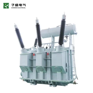
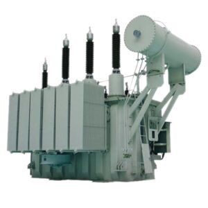
Transformer Tertiary Winding Specification for African Industrial Projects: Duty, Loading and Bid Evidence
Transformer tertiary winding specification should begin with the duty the winding must perform, not with an assumed percentage of the main transformer rating. For an African industrial project, a tertiary may be proposed for system performance, an auxiliary supply, reactive equipment, or a combination of approved duties. Those possibilities require different evidence. An internal stabilizing winding is not automatically an available power source for the plant.
The procurement decision is therefore simple to state: identify the intended function, agree the simultaneous loading cases, and make the manufacturer show how the offered design meets them. This guide provides seven review gates for EPC buyers. It is a specification and evidence framework; the final winding design, protection settings and operating limits remain project-specific engineering decisions.
1. Define the transformer tertiary winding specification by function
Ask the system designer to write a short duty statement before the RFQ is issued. Does the proposed winding serve only a stabilizing function? Must it supply a station service transformer? Will it connect to a reactor, capacitor installation or another external circuit? Is future loading a firm requirement, a priced option or simply a possibility? The answer should appear consistently in the single-line diagram, datasheet and bid schedule.
Do not use the phrase “delta tertiary provided” as a complete specification. It says little about external accessibility, permissible loading or the equipment needed to use it. An internally closed winding and a winding brought out to bushings create different interface and inspection requirements. If a supplier proposes a different arrangement, request a marked drawing and an explanation of the consequences for the project.
Research on tertiary stabilizing windings in three-legged YNynd transformers identifies their influence on zero-sequence behavior. The procurement implication is to obtain the actual design data needed by the project study, rather than treating every tertiary as an interchangeable accessory.
2. Separate the winding rating from the simultaneous loading envelope
A tertiary nameplate rating alone does not describe all permissible combinations of main and tertiary loading. Request a schedule that identifies the main winding loads, tertiary load, power factor, cooling mode, ambient assumptions and duration for each contractual case. The manufacturer should confirm the allowable combinations and identify any restrictions in its technical offer.
For an industrial plant with staged expansion, label the cases clearly: initial operation, ultimate demand, a defined outage condition and any proposed emergency duty. Do not quietly convert an emergency condition into continuous service. If some loads are not yet selected, give the supplier an explicit design envelope and a date for final reconciliation.
A useful bid response distinguishes guaranteed performance from provisional study inputs. For example, the purchaser may supply an estimated auxiliary load while the supplier confirms the offered winding capability subject to a stated harmonic envelope. That qualification should remain open until the actual load information is approved; it should not disappear into a general “complies” statement.
3. Request the electrical data that the studies actually need
The transformer tertiary winding specification should require winding connections, terminal designations, rated voltages, phase displacement, tap arrangement and the relevant impedance information. For a multiwinding design, ask the study engineer which winding-pair data and bases are required. A single impedance percentage copied from a two-winding datasheet may leave the network model incomplete.
Specify how the supplier will state reference power, reference temperature, tap position and tolerances. Ask for the applicable zero-sequence information and any limitations of the proposed equivalent circuit. If the tertiary is not externally accessible, agree how the required design information and available test evidence will be provided. Do not promise a site measurement that the physical arrangement cannot support.
The studies should use a common revision of this dataset. If the supplier changes a winding rating, connection or impedance during design development, the project engineer should identify which fault, protection, voltage or loading studies need to be updated. See the related guide on transformer short-circuit withstand evidence for organizing the fault-duty review.
| Обзор товара | Buyer input | Required supplier response | Опубликовать доказательства |
|---|---|---|---|
| Function and access | Duty statement and single-line diagram | Stabilizing, load-carrying or combined role; accessible terminals | Agreed winding and terminal diagram |
| Loading | Simultaneous operating cases and load characteristics | Permissible combinations and cooling assumptions | Approved loading schedule with restrictions |
| Network model | Study data requirements | Relevant impedance, connection and sequence data with bases | Controlled study input sheet |
| Fault duty | System fault cases and clearing assumptions | Applicable withstand evidence and design limits | Accepted engineering review |
| External interfaces | Cable, bus, switchgear and auxiliary supply scope | Terminal arrangement, ratings and responsibility boundaries | Approved interface drawings |
| Принятие | Contract test and document requirements | Test coverage, exclusions and traceable reports | Closed deviations and release dossier |
4. Review connected loads and future use explicitly
If the tertiary will feed auxiliaries, the purchaser should provide a load list that separates steady demand, motor starting, intermittent duty and nonlinear equipment. Identify the downstream transformer or switchgear where applicable. An aggregate kW total is not a substitute for the electrical characteristics that determine the complete supply arrangement.
For reactive equipment or power electronic loads, give the transformer supplier the relevant study assumptions and equipment data. Assign responsibility for checking interactions across the interface. A supplier cannot confirm an undefined future converter, capacitor bank or feeder merely because its apparent power appears smaller than the tertiary rating.
Future use should have a contractual status. An installed terminal provision may save later mechanical work, but it does not automatically reserve thermal capacity, protection coverage or switchgear space. State what is included now, what remains an option and what engineering review will be required before a later connection. For the plant-side boundary, use the auxiliary power supply design checklist.

5. Draw the protection boundary before approving terminals
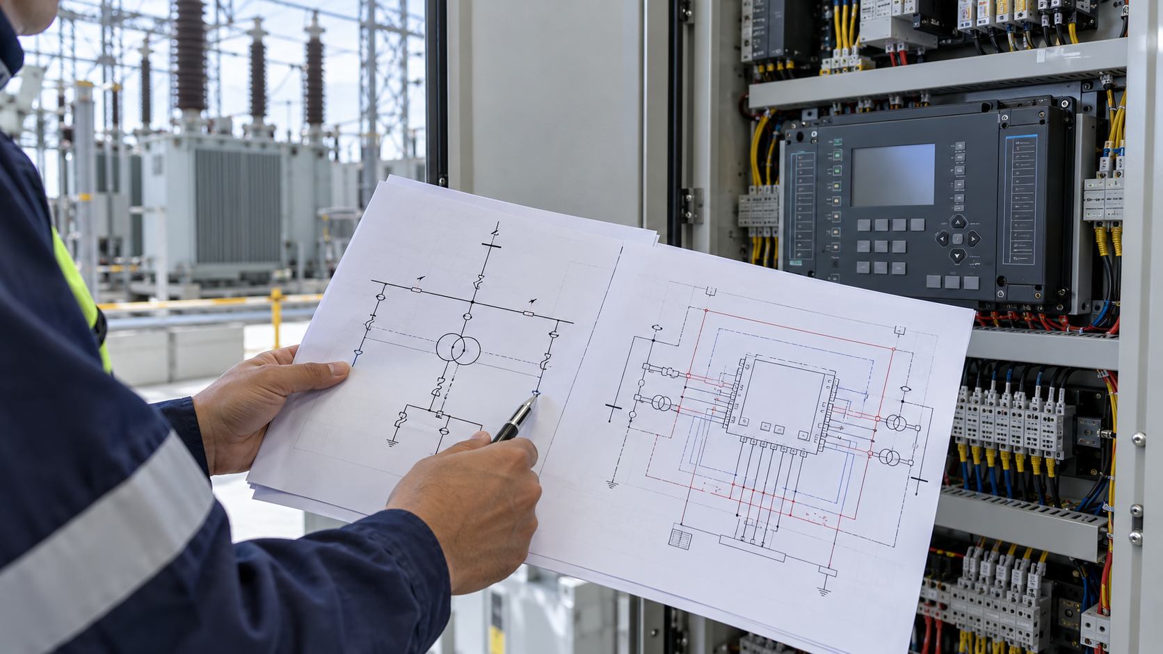
An external tertiary circuit creates questions about current transformers, relay inputs, fault detection, isolation and trip ownership. Ask the protection engineer to mark the zones on the single-line diagram. Identify which faults belong to the transformer scheme and which belong to the connected feeder or downstream equipment. Every boundary needs a named owner.
Relay family names are insufficient evidence. For example, SEL’s multiwinding transformer relay range distinguishes configurations intended for different numbers of windings. This illustrates why the actual relay model, input arrangement and approved application must be checked. It is not a recommendation to select a relay without a protection study.
The review should also cover CT locations, ratios, polarity, available cores and secondary wiring interfaces. Where a tertiary is internal and has no external load terminals, request the manufacturer’s proposed protection basis rather than assuming that an external feeder scheme applies. Record any design limitation in the accepted specification.
For a remote industrial site, ask who will maintain the completed arrangement. Spares, test access and drawing quality affect how quickly a fault can be investigated. These operational questions belong in the procurement review because correcting them after manufacture may require physical changes.
6. Align the mechanical interface and acceptance plan
Where terminals are brought out, compare the general arrangement drawing with the proposed cable or bus connection. Confirm phase identification, termination orientation, connection loads, access for installation and the equipment responsible for isolation. The project layout must also account for the associated switchgear and any auxiliary transformer.
Ask for the applicable insulation and surge coordination inputs rather than copying the main winding values onto the tertiary. The system engineer should establish the required insulation coordination, while the supplier identifies the offered terminal and winding characteristics. Keep that agreement traceable to the relevant drawings and approved study.
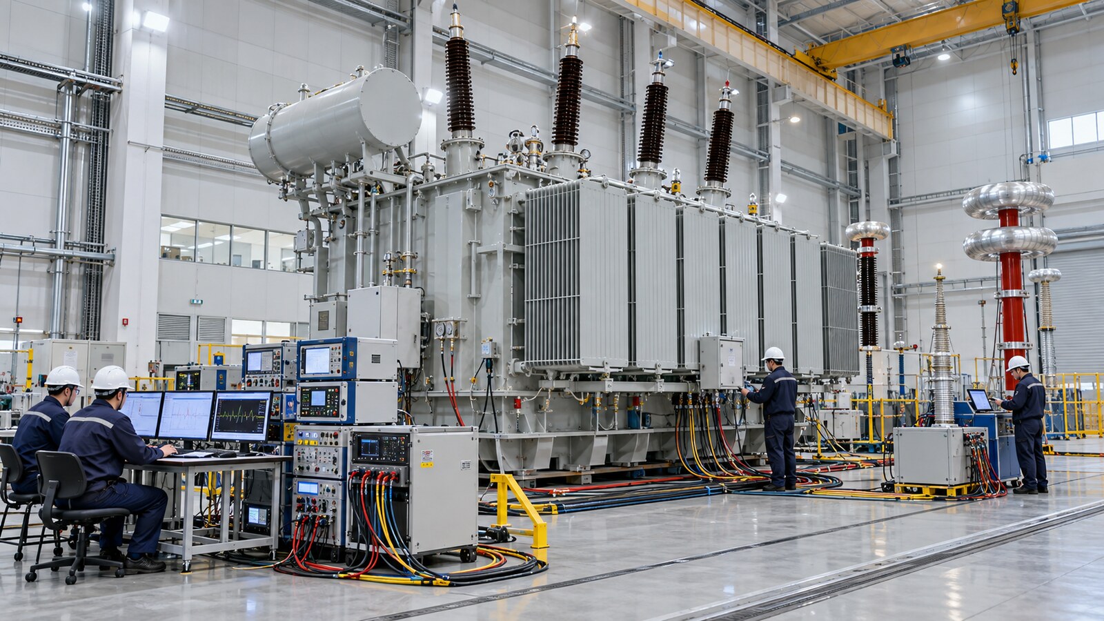
The factory acceptance plan should state which contractual checks cover the tertiary and how each result will be identified. Include the applicable connection, ratio, resistance, loss, impedance and dielectric evidence as agreed for the particular construction and contract. The available test arrangement may differ between accessible and internal windings; resolve that difference before the witness visit.
For each report, retain the equipment serial number, drawing revision, tested configuration and acceptance reference. If a result requires interpretation or a concession, obtain the engineering disposition before shipping release. A complete PDF bundle is useful only when the reports relate to the approved design.
7. Close the bid with a usable decision record
The final transformer tertiary winding specification should leave the purchaser with an identifiable configuration, an accepted loading envelope and a clear evidence plan. Compare bids against that common basis. A lower-priced offer that excludes external terminals or relies on a different loading assumption is a different scope until the discrepancy is resolved.
Use a short decision register with the issue, supplier response, engineering assessment, commercial effect, owner and closure reference. Keep unresolved items visible through drawing approval and factory release. The technical deviation register guide explains how to keep an exception connected to its final acceptance.
Consider an illustrative plant that initially requests a stabilizing winding and later decides to supply a workshop from it. The correct next step is a design change review covering the external circuit, loading, protection and physical interfaces. It is not merely a request to add an outgoing cable. This example is a planning scenario, not a claim about a completed Zisheng project.
Frequently asked questions
Does every power transformer need a tertiary winding?
No. The need depends on the system arrangement and the design objectives. The purchaser should request an engineering justification for including or omitting one, particularly when its role affects the network studies.
Can a stabilizing winding supply factory auxiliaries?
Only if the manufacturer has designed and rated it for the intended external duty and the complete connection has been approved. The presence of an internal winding alone does not establish a usable auxiliary supply.
Is a fixed percentage of the main rating a sufficient specification?
No. A percentage does not define simultaneous loading, connected load characteristics, fault duty or cooling conditions. Specify the required cases and obtain the manufacturer’s confirmed capability.
Should the RFQ request all winding-pair impedances?
The study engineer should define the required dataset for the proposed transformer. Request the relevant winding-pair information with clear bases, test conditions and tolerances, and identify any limitations in the supplier’s response.
What information should buyers send first?
Send the single-line diagram, main winding ratings, tertiary duty statement, operating cases, connected load data and the project study requirements. Include the site conditions and the expected division of supply.
Prepare a project-specific technical enquiry
Share those inputs with Zisheng for a coordinated transformer and interface review. Ask the team to identify the proposed design, exclusions and evidence still needed before an offer can be approved. Related power-transformer products can be a starting point for the discussion; their standard listings should not be interpreted as confirmation that a tertiary winding is included.
О компании ZISHENG ELECTRICAL
Жишэнг является профессиональным производителем с более чем 19-летним опытом масляных трансформаторов, Компактная подстанция, Трансформаторы в пневматических установках, полевые трансформаторы и Сухие трансформаторы. У нас есть сертификаты ISO/CE/IEC 60076 и TUV Rheinland.
Трансформаторы проходят строгие испытания FAT и аттестацию типа, поддерживают настройку напряжения/емкости. Добро пожаловать на консультацию по Каталог и Продукт. вы можете связаться с нами по электронной почте [email protected].