Electric Bus Depot Transformer for Latin American Fleets: Charging Duty, Harmonics and Expansion
Zisheng Electric s'apprête à electric bus depot transformer as part of an operating schedule, rather than a fixed number of chargers multiplied by their nameplate ratings. For a Latin American bus operator, a depot may return a large fleet within a narrow evening window, charge several vehicles at different powers, then dispatch them before dawn. The transformer has to support the resulting real load, the charger power electronics and the next phase of fleet growth. A tender based only on the sum of connector ratings can oversize the equipment; a tender based only on average energy can leave the depot unable to dispatch.
This guide is for fleet owners, EPC contractors, charging developers and electrical distributors preparing a request for quotation. It gives a practical method for turning route schedules into transformer requirements. The actual voltage, frequency, utility connection rules, climate data and site permissions must come from the project documents and the relevant local authority. Latin America is not a single electrical system, and no universal connection voltage is assumed here.
Start the electric bus depot transformer study with the operating timetable
Ask the fleet planner for vehicle arrival time, state of charge, next departure, battery energy to be replaced and the maximum charging power each vehicle can accept. Distinguish the connector rating from the charging power sustained over the session. A vehicle may taper its power as its battery fills, while a charger may be shared between two bays. The electrical engineer should build a time series in short intervals and identify both the highest coincident power and the energy that must be delivered before dispatch.
For each interval, add charger input demand, depot lighting, ventilation, workshops, wash plant, HVAC and other auxiliary loads. Include charger conversion losses using the supplier’s stated input data, not an assumed efficiency copied from another model. Apply diversity only when backed by a dispatch rule or power management system that the operator is willing to enforce. A charger can be available without drawing full power; conversely, a late fleet return can concentrate sessions unexpectedly.
Test the bad night, not only the average night
A normal day is not the design boundary. Consider a delayed route, a missed daytime top-up, unusually high auxiliary demand, one charger out of service and a temporary curtailment request from the utility. Model how many buses can still reach their required departure charge. If the depot relies on software to keep the transformer within a limit, specify what happens on loss of communications, bad metering, manual override and charger restart after an outage. The transformer rating and the control philosophy must agree.
Write down whether the transformer must carry an emergency charging schedule without the management system. Where that is economically unreasonable, state the operational limitation plainly and obtain the fleet owner’s approval. A nominally adequate unit is not adequate when the only credible recovery schedule exceeds its agreed loading envelope.
Convert the charging profile into an electrical specification
Separate the transformer continuous rating from short periods of high demand. Thermal behavior depends on ambient conditions, previous loading and cooling arrangement, so a short peak cannot be declared harmless merely because the daily average is low. Request the supplier’s temperature rise and loading evidence for the proposed duty. The assessment should distinguish the bus charging window from the rest of the day and include realistic initial temperature.
At the low-voltage side, the charging equipment may be installed in clusters. Measure or obtain the cable lengths and feeder sizes, then check voltage drop during simultaneous operation. A central transformer may simplify one point of utility interface but create long low-voltage runs. Several smaller transformers can shorten those runs while adding protection, metering and maintenance interfaces. Compare both arrangements on installed cost, fault level, service continuity and accessible space.
| Decision input | Pièces à demander | Engineering consequence | Bid response to compare |
|---|---|---|---|
| Fleet arrival and departure windows | Time-stamped schedule, energy per bus and charger power curve | Sets coincident demand and recovery window | Rating and supported charging schedule |
| Charger input behavior | Vendor harmonic spectrum, power factor and input current at representative load | Changes winding and cable heating, protection and power-quality study | Guaranteed operating conditions and thermal basis |
| Utility connection | Approved point of connection, voltage range, fault level and metering arrangement | Sets insulation, tapping, fault duty and ownership boundary | Interface drawing and proposed tap range |
| Site and climate | Measured ambient range, altitude, drainage and available footprint | Affects cooling, enclosure, access and civil design | General arrangement and site derating statement |
| Fleet expansion | Phased charger count and approved demand limit | Determines whether to reserve space or buy capacity now | Initial and expansion configurations |
The table is a bid comparison tool, not a set of universal limits. Project-specific acceptance values belong in the employer’s requirements. The same physical transformer can be a good offer for one charging pattern and a poor offer for another.

Check harmonic currents and protection at the charger interface
Modern DC chargers use converters. Their actual current spectrum depends on design, load and controls; it should be supplied by the charger manufacturer or measured on an existing installation. Harmonic currents may increase losses in transformer windings and nearby conductors. Ask the transformer supplier to state the harmonic loading basis used for its thermal design, and ensure the power-quality study uses the same charger operating scenarios. A generic statement that a transformer is “harmonic capable” is too vague for a purchase specification.
Check the highest prospective short-circuit current with the selected transformer impedance and utility contribution, then confirm the low-voltage switchgear and charger feeder protection ratings. At the other end of the range, consider a weak supply and remote faults so that protection still detects and isolates faults selectively. Charger manufacturers should provide start-up, inrush and ride-through behavior. Protective devices must coordinate with the actual equipment rather than an abstract charger block on a one-line diagram.
Electrical distribution concepts discussed in the site’s EV charging transformer selection guide provide background. For a depot, however, the bus timetable and the charger vendor’s data decide the final duty. A comparable approach to converter interfaces appears in the BESS transformer discussion, while the railway depot specification illustrates why a site’s particular load behavior must be described before selecting equipment. These links address related engineering questions; they do not substitute for a depot-specific study.
Choose the physical arrangement around maintenance and expansion
Lay out the vehicle circulation, charger pedestals, pedestrian paths, transformer access, cable route and fire response access together. The transformer should not require moving buses or disconnecting charging equipment for routine inspection. Confirm how it will be lifted or replaced after the depot is operating. A compact electrical footprint can become a costly maintenance trap if no delivery path remains.
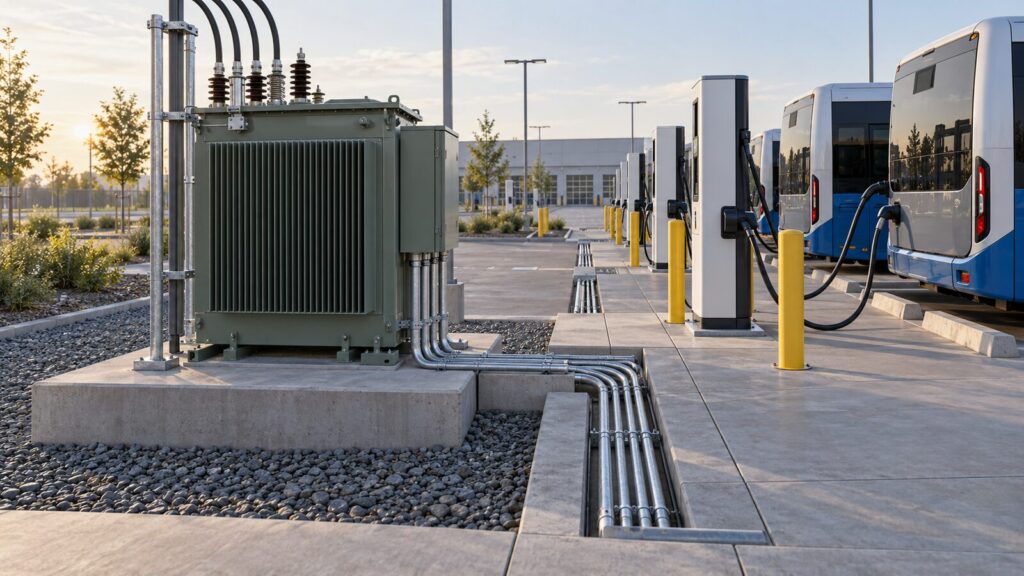
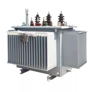
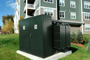
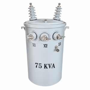
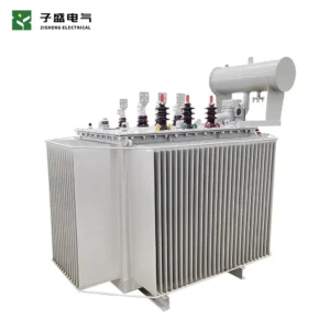
For outdoor distribution, a pad mounted transformer range may suit a fenced charging compound where the project voltage and ratings match. A distribution transformer range offers other configurations for the same evaluation. Larger depots or a medium-voltage charging network may call for a ensemble de transformateurs pour sous-station. These are product families to review, not a claim that any listed catalog rating meets a particular bus depot. Confirm the selected model against the site data and approved single-line diagram.
Where a utility requires dedicated metering or switching, show its location and ownership on the drawings. Do not assume the utility will accept a privately selected arrangement. Reserve enough civil space and cable routes for the approved expansion, even if the first transformer is sized for an initial fleet. A staged second unit may provide better resilience and cash flow than a large first unit, but the bus operator must accept the transfer and outage behavior.
Evaluate a single large unit against two smaller units
A single unit is simple to procure and can reduce the number of switchgear bays. It also creates a common outage affecting the whole depot unless there is another supply path. Two units can separate charging zones, allow phased purchase and support partial operation during maintenance. They introduce additional protection and possible bus-tie operating rules. Compare the alternatives using an operating scenario with one unit unavailable, not only a full-capacity case.
If parallel operation is proposed, confirm compatible voltage ratios, vector groups, tap positions, impedance characteristics and protection settings with the suppliers. If the units operate separately, define how chargers are allocated and whether the energy management system can move capacity across zones. These details have direct consequences for service continuity and cannot be deferred until commissioning.
Specify the utility boundary without assuming a national template
Latin American markets contain different utility practices and connection arrangements. The project team should obtain an approved connection study, point-of-connection drawing, permitted demand, fault-level information, supply voltage and frequency, metering scope, power-factor requirements and any power-quality limits applicable to the actual site. Where values remain pending, label them as open inputs in the request for quotation and request a priced or technical alternative. Do not insert a familiar voltage just because it appears in an earlier project.
Check the site’s altitude, ambient temperature, moisture, flood level and any coastal exposure from survey data. The outdoor enclosure, corrosion protection, cooling method and cable entries should reflect that evidence. A depot in a dense city may face access, noise and footprint constraints; an inland site may have a different thermal and logistics problem. The procurement document should make the conditions measurable and identify who supplies any missing data.
Charging network growth can change the connection agreement. Ask whether the utility approves the full ultimate demand or only the first phase. If a demand cap is binding, specify monitoring accuracy, alarm response and control fallback. The transformer purchase should not imply that the utility has approved higher demand.
Write a bid package that exposes real differences
Issue one schedule covering continuous rating, winding voltages, frequency, tap requirement, impedance basis, cooling, installation type, ambient and altitude, charger harmonic data, noise requirement, accessories, monitoring, tests, transport split, documentation and spare parts. Require bidders to identify deviations line by line. Ask for both a guaranteed-loss schedule and a thermal explanation tied to the charging profile. An unqualified catalog sheet may hide differences in losses or protection interfaces.
Request a general arrangement showing the transformer, access clearances, cable entries, earthing points and lifting path. The depot civil designer can then check transformer dimensions against drainage, containment and bus circulation. Define the factory test records and delivery inspection evidence that will be handed to the operator. If the project includes commissioning support, identify the contractor responsible for secondary wiring, relay settings, charger energization and final integrated tests.
Compare offers by normal operation, delayed-fleet recovery, one charger unavailable, one transformer unavailable and fleet expansion. Ask each bidder to state where a proposed rating relies on enforced charging limits. The most useful comparison is a short narrative showing what the depot can actually do in each case, not a price column alone.
Decision for the next procurement gate
La electric bus depot transformer should be selected only after the fleet charging schedule, charger input data and utility boundary have been reconciled. Zisheng Electric can review relevant pad mounted, distribution and substation transformer options against the electrical and physical requirements. Send the drawings, equipment datasheets, load list, technical specification, single-line diagram, grid parameters, environmental conditions and installation-site conditions, together with a time-stamped charging profile and the proposed expansion phases. Our engineering team will review the requirements and respond to project inquiries within 24 hours.
À propos de ZISHENG ELECTRICAL
Zisheng sont un fabricant professionnel avec plus de 19 ans d'expérience dans la production Transformateurs immersés dans l'huile, Sous-station compacte, Transformateurs montés sur socle, Transformateurs montés sur poteau et Transformateurs à sec. Nous possédons les certificats de ISO/CE/IEC 60076 et TUV Rheinland.
Les transformateurs subissent des tests de FAT rigoureux et des essais de type, prenant en charge la personnalisation de la tension/capacité. Bienvenue pour consulter pour Catalogue et Produit. vous pouvez nous contacter par email [email protected].