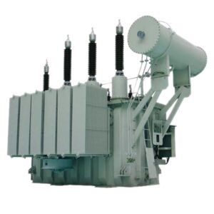
Transformer Protection CT Saturation Review for African Industrial Projects: Stability, Burden and Relay Checks
Zisheng Electric works with EPC engineers and industrial buyers to coordinate transformer ratings, external current transformers, protection relays and commissioning evidence. A CT saturation review is useful when a transformer differential or overcurrent scheme must remain dependable during high-current faults, especially where long secondary leads, multiple CT cores or high system fault levels shape the protection circuit. The review is not a substitute for a short-circuit study or a relay application study. It is a structured way to test whether the installed CT, wiring and relay assumptions remain consistent for the actual project.
CT saturation is often discussed as if it were a single nameplate check. In practice, performance depends on the primary current waveform, the CT magnetic characteristic, secondary burden, remanence, lead resistance, connected devices and relay algorithm. A procurement decision made from ratio alone can therefore miss the condition that matters most: whether the complete protection circuit can reproduce enough current information during the relevant fault cases for the relay to make a secure and timely decision.
Transformer protection CT saturation review: what the study must answer
The first question is not simply “Will the CT saturate?” Every iron-core CT has a finite excitation characteristic, and saturation can occur under sufficiently demanding conditions. The engineering question is whether the degree and timing of saturation could compromise a particular protection function. For transformer differential protection, the review should consider external through-fault stability, internal-fault dependability, inrush restraint or blocking, and the relay’s treatment of distorted or missing current samples. For backup overcurrent protection, the focus may instead be fault-current measurement, coordination time and the duration of useful secondary output.
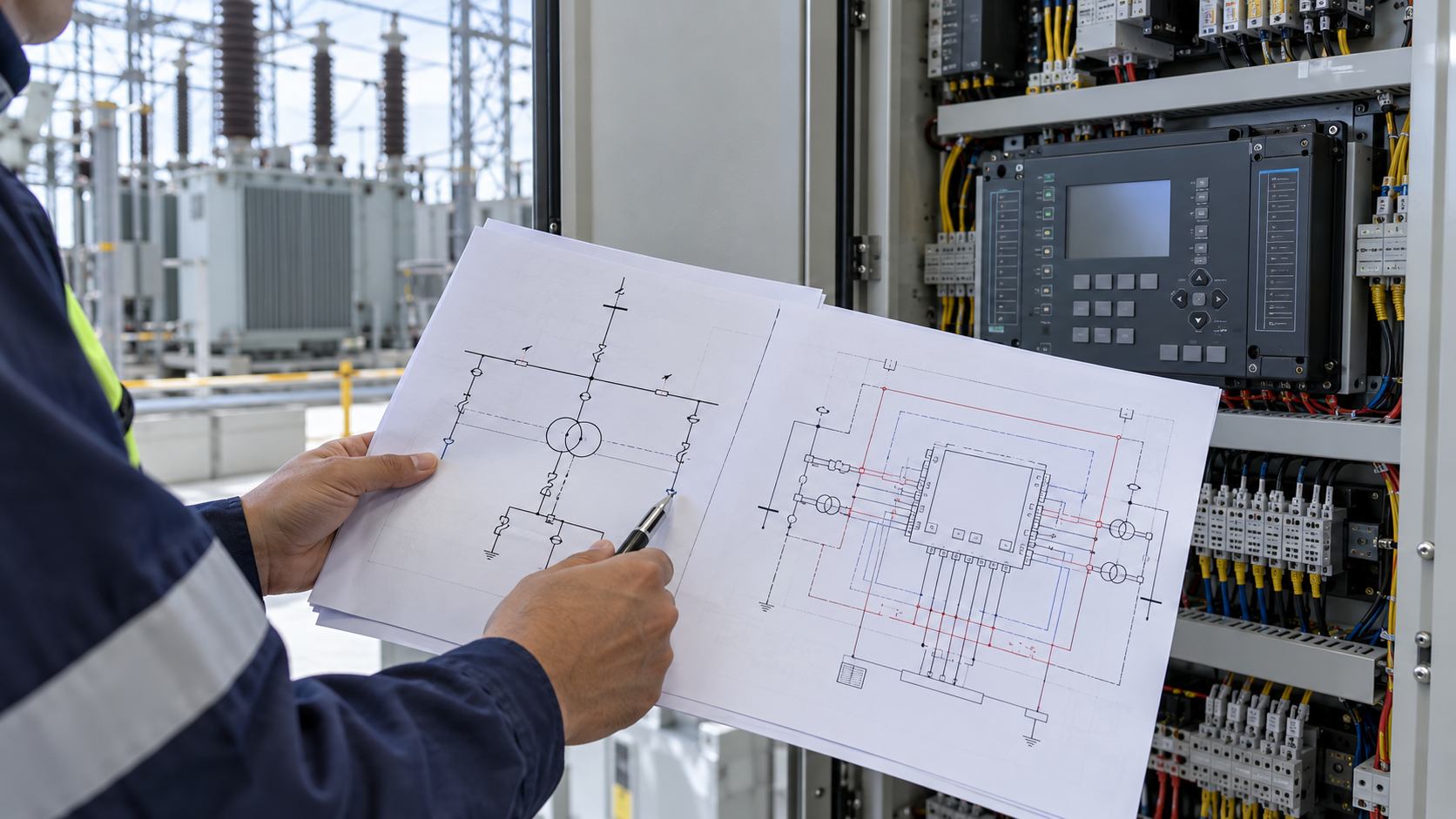
Define the protected zone before collecting data. Identify the transformer winding CTs, any switchgear CTs included in the differential zone, neutral CTs, bus-zone boundaries and breaker locations. A one-line diagram with CT polarity marks is more valuable than an isolated CT schedule because it shows which currents the relay compares and where through-current can create unequal saturation. The relay manual and approved setting file also matter; a numerical assumption about bias, restraint or saturation detection should not be inferred from a generic relay family name.
Collect a complete and traceable data set
For each CT core, collect the ratio, secondary rating, protection class or specified accuracy limit, rated burden, knee-point or excitation data where applicable, winding resistance, polarity, terminal arrangement and manufacturer’s test certificate. The standard designation must be preserved exactly. IEC and IEEE classifications do not map one-to-one in every application, and class alone does not demonstrate performance for a specific asymmetrical fault. Where a project specification calls for a particular transient performance class, record that requirement and the evidence offered by the supplier rather than translating it informally into another standard’s label.
Collect the system inputs that determine the primary current: maximum and minimum short-circuit levels, X/R ratio or another approved representation of the DC component, fault location, fault inception angle assumptions if the study uses them, and the protection clearing time. Include transformer impedance, winding connection, grounding method, source contribution on both sides, parallel transformers, generator or motor contribution, and any relevant bus coupler state. The fault case at the remote system boundary may differ materially from the close-in fault that drives CT voltage highest.
Secondary-circuit information is frequently incomplete. The review needs the one-way cable route length, conductor material and cross-section, actual terminal and test-block arrangement, number of connected devices, relay input burden, meter connections, shorting links and any shared cores. A long route in a large industrial plant can add meaningful resistance; a shared metering circuit may increase burden or introduce maintenance risk. The CT loop is the entire connected circuit, not only the instrument cable shown on one drawing.
Understand how saturation develops
A CT secondary current attempts to balance primary ampere-turns. The secondary voltage needed to drive that current through the loop is shaped by loop impedance and the waveform. During a severe fault, the required flux may exceed what the core can reproduce linearly. A decaying DC component associated with an asymmetrical fault can drive the core toward saturation earlier on one polarity than a symmetrical RMS value suggests. Residual flux from a previous event can further reduce the available margin in one direction. These conditions do not mean every fault will saturate every CT; they explain why a simple ratio-times-fault-current comparison can be inadequate.
CT performance may differ between transformer sides because ratios, core sizes, secondary wiring and fault contributions differ. Differential relays often compensate for ratio and vector-group differences internally, but that compensation does not make unequal CT transient behavior disappear. The engineer should use the relay manufacturer’s documented application method and the project’s adopted protection philosophy. If a transient simulation is warranted, keep the primary waveform, CT model, loop burden and relay behavior consistent and identify which results are measured, calculated or assumed.
Decision matrix for the EPC review
| Review input | Comprobación técnica | Decision supported |
|---|---|---|
| Fault current and X/R | Check maximum close-in and external through-fault cases, including the clearing interval and approved DC-offset model. | Whether transient CT performance needs detailed calculation or simulation. |
| CT core data | Match ratio, class, excitation curve, resistance and certificate to the protection function. | Accept the specified core, request evidence or revise the core specification. |
| Secondary loop | Calculate total loop resistance and include relay, test switch and connected-device burdens. | Increase conductor size, shorten route, assign a dedicated core or recheck CT selection. |
| Differential scheme | Check winding CT locations, polarity, ratio compensation, restraint and external-fault stability. | Confirm the relay application or send a revised setting/application package for review. |
| Commissioning evidence | Verify ratio, polarity, continuity, grounding, shorting links and phase identification. | Release the circuit for protection injection and controlled functional testing. |
Calculate the connected burden, not a catalog assumption
For a conventional CT secondary circuit, the approximate burden voltage is related to secondary current and total loop impedance. The loop resistance includes both outgoing and return conductors, terminations, test switches, shorting blocks and connected inputs. Use the manufacturer’s stated convention for cable length: some schedules list route distance while the electrical circuit includes a round trip. Do not double-count or omit the return path. Verify conductor temperature assumptions when they are material to the design, and use actual cable data where a long distance makes it significant.
Separate measurement cores from protection cores where the design and procurement basis require it. A core shared across functions can create competing requirements for accuracy, burden and maintenance isolation. The final arrangement must align with the relay manufacturer’s input range and the owner’s metering requirements. If the connected burden exceeds the specified CT capability, options may include reducing lead resistance, assigning a dedicated core, revising the CT specification or reviewing the protection architecture. Any change must be checked against the actual fault duty and relay requirements, not made solely to improve a calculated margin.
Review differential protection as a system
For transformer differential schemes, confirm the CT ratios and locations on all protected windings, CT polarity, phase compensation or vector-group compensation, zero-sequence treatment where applicable, and the relay’s settings for restraint and differential thresholds. Check the expected current balance for normal load and external faults, then assess how unequal saturation could affect the relay’s measured operating and restraint quantities. The objective is to demonstrate adequate stability for the declared external-fault cases while preserving sensitivity to internal transformer faults.
Do not assume a higher CT ratio always improves performance. It can reduce secondary current for a given primary fault but may also reduce sensitivity or affect the relay’s usable range. Likewise, a higher nominal accuracy class does not automatically guarantee the transient response needed for every asymmetrical fault. The selected CT should meet the system-specific duty and the project standard, with the evidence and assumptions recorded. Where the relay includes saturation detection or waveform-based restraint, confirm its operating conditions and limitations in the approved manufacturer documentation.
For phase overcurrent, restricted earth fault, standby earth fault or bus protection, perform a separate function-by-function review. A conclusion for the transformer differential core does not certify another core or another protection element. The CT ratio, residual connection, neutral location and earth-fault current path may differ. List each protection function, its CT core, expected maximum current, connected burden and acceptance evidence in the calculation package.
When a detailed transient study is justified
A project may use a documented engineering calculation where the fault duty is moderate and CT data are complete. A more detailed transient study may be justified when the maximum fault current and X/R are high, the protection zone has unequal CTs, the secondary burden is substantial, a critical process cannot tolerate an unwanted trip, or the relay supplier requests specific evidence. A simulation should state its CT magnetization model, remanence treatment, primary current waveform, burden, relay algorithm assumptions and output criteria. A plot without input data and acceptance criteria is not a reproducible engineering result.
Define pass/fail criteria before running the analysis. These may include relay stability for named external-fault cases, a required operating time for internal faults, or agreement with a manufacturer’s application guidance. The owner, EPC protection engineer and relay supplier should agree who approves the model and who owns any setting changes. Do not set a universal numerical saturation limit in the article or procurement document where the relay application, CT design and fault duty have not been specified.
Procurement and drawing controls
Put the requirements in the transformer and switchgear interface documents. The CT schedule should identify each core’s function, ratio, terminal markings, class, burden or performance requirement, test certificate and associated relay. The protection single-line diagram, AC schematic, terminal plan, cable schedule and relay input list should use consistent designations. For transformer supply packages, confirm which CTs are included in the transformer scope and which belong to switchgear or bus equipment. A scope gap at this interface can leave the project with the right relay but the wrong CT or incomplete test evidence.
At design review, close every exception with an owner and a drawing or calculation reference. If the CT vendor proposes an alternative core, check the excitation data, winding resistance, physical dimensions, terminal arrangement and test certificate against the original basis. Avoid accepting phrases such as “equivalent CT” without a documented comparison. The change may affect settings, relay stability, cable sizing or maintenance isolation and should be assessed before manufacturing release.
Commissioning checks that close the loop
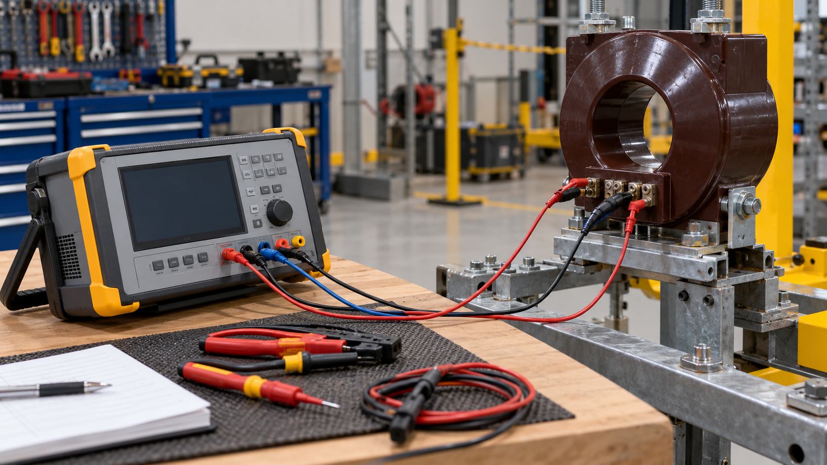
Before energization, verify installed CT identity against the approved drawings, confirm phase labels and polarity, inspect shorting links and test blocks, check secondary continuity, verify single-point secondary grounding according to the approved scheme, and confirm there is no open-circuit CT secondary while primary current can flow. Perform ratio and polarity tests using the agreed method and compare results with the certificate and wiring diagrams. Record test instrument identification and calibration status where required by the project quality plan.
Secondary injection can demonstrate relay logic and wiring behavior, but it does not by itself prove the CT’s transient performance under a high primary fault. Primary injection may verify the complete CT path and relay measurement if the test setup and isolation boundaries permit it. The final report should distinguish these test purposes. Capture the relay setting version, disturbance-recording configuration, test results, punch items and approved deviations. A clear record allows later investigation to compare the field installation with the basis used for the study.

Common review errors
- Using only symmetrical RMS fault current while ignoring the system X/R and transient offset where relevant.
- Calculating burden from cable length without checking whether the schedule gives one-way route distance or complete loop length.
- Assuming CT class or ratio alone proves relay stability.
- Using one winding’s CT assessment to approve every protection function or core.
- Changing a CT or conductor size without reviewing relay sensitivity, drawings and settings.
- Calling secondary injection a demonstration of performance during a primary high-current fault.
For related project context, review Zisheng Electric’s transformer protection coordination guide, CT ratio, class and burden specification article, short-circuit withstand evidence guide y harmonic heating assessment. For equipment context, see the 220/230 kV power transformer y 138–150 kV three-phase oil-immersed transformer product pages.
For standards context, IEC 61869-2:2012 covers requirements for newly manufactured inductive current transformers in its stated scope, while IEEE C37.110-2023 is a guide for applying current transformers used for protective relaying. Use the project-adopted editions and the complete standard text for design decisions; the official publication pages are IEC 61869-2 y IEEE C37.110-2023.
For a project-specific transformer protection CT saturation review, provide the protection single-line, CT schedules and certificates, maximum and minimum fault data including X/R, relay model and approved settings, secondary cable routes and conductor sizes, and the site grounding and operating configuration. Zisheng Electric can coordinate transformer CT interfaces and supporting technical records with EPC and protection teams. Our engineering team will review the requirements and respond to project inquiries within 24 hours.
Acerca de ZISHENG ELECTRICAL
Zisheng somos un fabricante profesional con más de 19 años de experiencia en la producción de Transformadores Sumergidos en Aceite, Subestación Compacta, Transformadores Montados en Base, Transformadores Montados en Poste y Transformadores de Tipo Seco. Poseemos los certificados de ISO/CE/IEC 60076 y TUV Rheinland.
Los transformadores pasan por rigurosas pruebas FAT y de tipo, y apoyan la personalización de voltaje/capacidad. Bienvenido a consultar por Catálogo y Producto. puede contactarnos por correo electrónico [email protected].