
Transformer Fire Protection Interface for Middle East EPC Projects: Containment, Separation and Controls
Zisheng Electric works with EPC teams that must fit a transformer into a complete industrial site, not merely select a nameplate. A transformer fire protection interface review asks how the equipment, oil containment, separation, detection, drainage and operating access will work together before concrete and cable routes are fixed. On a Middle East project, heat, dust and remote maintenance access can change the practical arrangement, but no single regional rule replaces the actual site specification, insurer conditions and authority review.
This guide is a project coordination checklist for oil immersed equipment. It does not prescribe a fire wall dimension, pit capacity, suppression system or clearance. Those are design outputs that depend on the approved fire strategy, transformer data and local authority. The most expensive errors often arise when every discipline assumes that another party owns a small interface.
Define the transformer fire protection interface before layout freeze
The first drawing should show the complete transformer envelope: tank, conservator or alternative oil preservation arrangement, radiators, cable boxes, bushings, marshalling cabinet, valves and lifting points. The civil drawing must show foundations, containment and drainage; the electrical drawing must show power and control cable routes; the fire strategy must show exposure boundaries, detection and any active protection. A plan with only the tank outline cannot prove that maintenance access or a fire barrier remains workable after accessories are installed.
Request the manufacturer’s general arrangement and oil volume at the same revision as the civil layout. If the bid allows alternative ratings or cooling arrangements, show the worst credible footprint and oil inventory until the purchase order freezes one design. A late radiator bank can shift a wall, narrow a vehicle route or move the edge of containment. The EPC coordinator should record who approves that change and whether it triggers a fresh fire review.
Separate the basis of design from assumptions
IEC 61936-1:2021 covers the design and erection of electrical power installations above 1 kV AC and explicitly includes transformers and associated systems. It is a useful framework, but the project must identify its applicable edition and any contractual deviations. FM’s transformer loss prevention data sheet gives insurer guidance for outdoor transformer fire protection and oil containment. Neither source makes a generic internet layout an approved local design. Record the authority having jurisdiction, owner criteria and insurer recommendations in the design basis, then resolve conflicts through the project’s formal deviation process. See the IEC publication overview y FM transformer data sheet for the source scope.
Oil containment is a system, not just a concrete rim
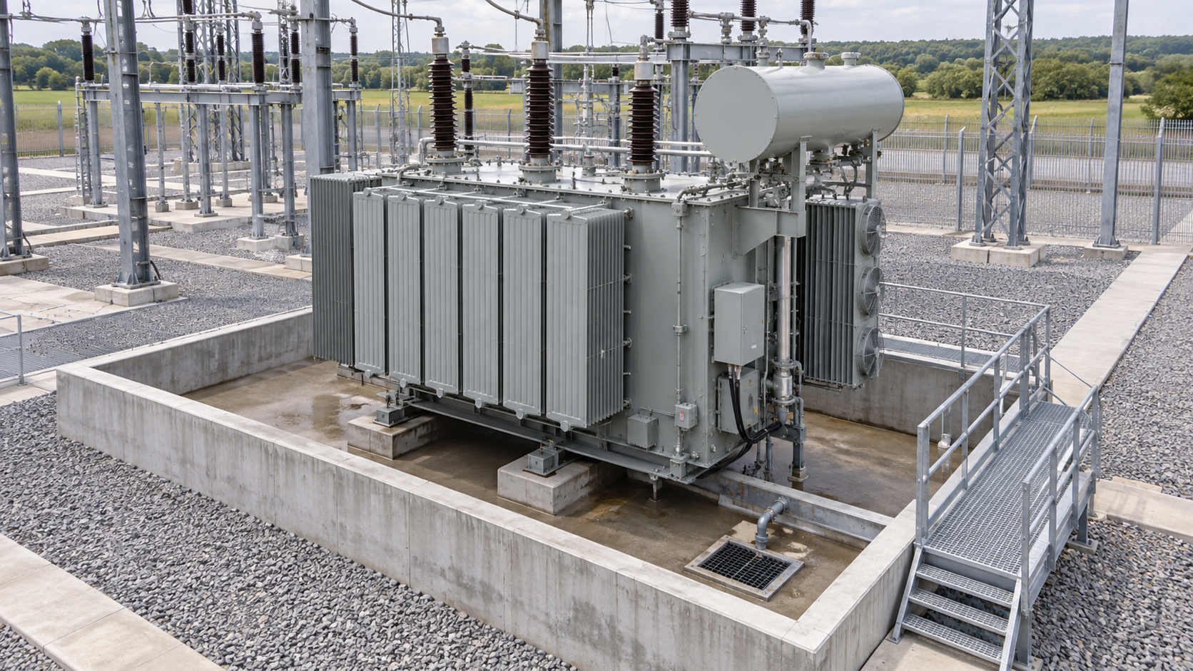
For an oil immersed transformer, the containment decision begins with the confirmed liquid inventory and credible release paths. Oil can leave a tank through fittings, radiators and pipework, not only a bottom drain. The designer must also address stormwater, firefighting water where applicable, slope, sediment and how a closed valve or separator will be operated. A pit drawn without an accessible inspection point is difficult to maintain; a drain connected to a general site network without a reviewed isolation strategy can move the hazard beyond the transformer bay.
Ask the civil and environmental teams to document their calculation basis and show it on a drawing. Verify whether the calculation includes more than one connected item of equipment, whether a common sump serves multiple bays, and how oil and rainwater are managed during normal operation. Do not copy a pit capacity from a different project. The correct arrangement depends on the project fire strategy and applicable environmental controls. A containment system must remain accessible after cable trenches, rails and walkways are built.
Interface decision register for bid and design reviews
| Interfaz | Input to request | Decision at layout freeze | Evidence at handover |
|---|---|---|---|
| Oil inventory and release | Certified oil volume, accessory schedule, valve locations | Containment basis and release paths agreed with civil and environmental leads | Approved calculation, as-built pit and drain drawings |
| Exposure and separation | Equipment envelope, adjacent assets, owner’s fire strategy | Wall or separation solution reviewed against access and future replacement | Approved layout, wall inspection records |
| Detection and control | Protection contacts, alarm philosophy, control supply | Signal ownership and cause-and-effect matrix signed by disciplines | Loop checks and functional test records |
| Suppression, if specified | Fire engineering basis, water or agent supply, vendor package boundary | Nozzle and pipework envelopes coordinated with live parts and maintenance | Installation and acceptance records required by project |
| Access and drainage | Transport route, lifting plan, trench and road levels | Emergency and maintenance routes remain usable | As-built access survey and operating instructions |
The table is a decision register rather than a compliance certificate. For each row, nominate an owner, revision and approval date. An unresolved assumption should be carried openly into the bid clarification log instead of disappearing behind a generic statement such as “by others.” This is especially important when the transformer supplier and EPC contractor have separate scopes.
Coordinate separation with the real equipment envelope
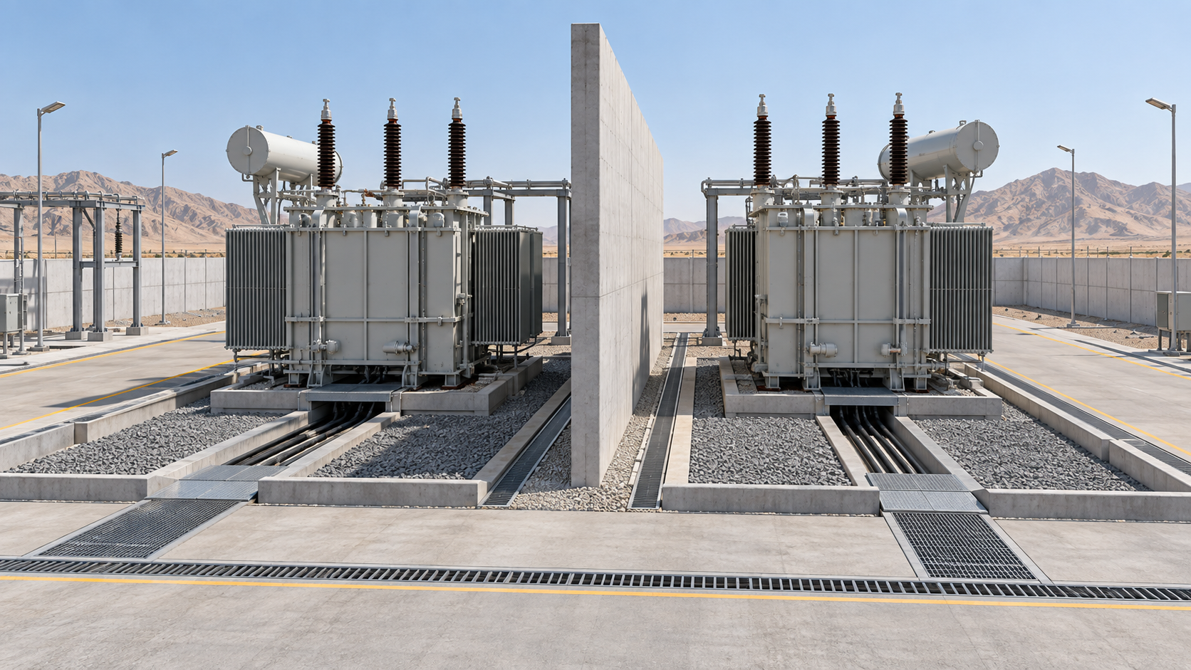
A separation wall or distance is intended to limit exposure between a transformer and nearby assets. Its usefulness depends on geometry, openings, relative elevations and the installed equipment, including radiators and conservator. A wall that clears the main tank can still obstruct lifting of a radiator or leave a cable termination outside the protected zone. A road drawn beside the wall may be too narrow for equipment replacement. The fire engineer must decide the required performance; the EPC team must make that performance buildable.
Map adjacent transformers, switchgear buildings, control rooms, pipelines and storage areas. Show future bays if expansion is in the project scope. Where a wall also supports other equipment, avoid assuming that its structural function and fire performance are automatically compatible. Civil, structural and fire specialists should approve penetrations, drainage openings and interfaces. If a project elects an alternative liquid or dry-type arrangement, recheck the actual fire strategy instead of assuming the substitution removes every site requirement. Zisheng Electric’s 132kV/138kV oil immersed transformer y S20 35kV oil immersed transformer pages illustrate different product envelopes that still require project-specific interface drawings.
Keep detection, protection and suppression scopes explicit
Electrical protection trips are not a substitute for a complete site fire response. The transformer may provide temperature, pressure or gas-related contacts according to its selected configuration, while a separate detection or suppression contractor provides devices and panels. The EPC design must specify which signals are alarms, which cause a trip, which initiate an automatic action and which require operator confirmation. The cause-and-effect matrix should identify the receiving panel, power supply, cable type, communication path and test method for each signal.
A common procurement gap is a phrase such as “fire protection contacts included” without a terminal schedule. Ask for a contact list with normal state, rating, terminal number and test provision. Then agree who supplies field cabling, marshalling, panel programming and integrated testing. If water-based protection is specified, the fire engineering team must check supply, hydraulics, electrical clearances, drainage and equipment accessibility; the transformer supplier should review physical clashes and any effect on supplied accessories. The applicable solution is project-specific, not a default add-on to every transformer order.
Protect the control system from ambiguous responsibilities
Include the transformer vendor, fire system vendor and electrical contractor in one interface meeting before cable schedules are finalized. Circulate a single marked-up termination drawing. If remote operation is required, establish what the control room will display during loss of communications or DC supply. A test that proves a lamp lights at the local cabinet does not prove the site’s full response. Define both factory tests for supplied devices and site tests for the integrated system, including safe simulation methods and restoration steps.

Make the Middle East site conditions actionable
“Middle East climate” is too broad to specify equipment. Obtain the design ambient range, solar exposure, dust conditions, coastal corrosion exposure, rainfall intensity and site elevation from the actual project data. These inputs affect cooling selection, enclosure details, external cable protection, inspection frequency and maintenance access. A coastal industrial site may need more attention to corrosion and contamination; an inland desert site may place greater emphasis on dust and cleaning access. Neither condition determines a single universal fire wall or containment dimension.
Show truck and crane routes on the same plan as the fire protection features. A tanker may need access to a filling point; a replacement transformer may need a route that crosses a drainage channel or passes a wall. Confirm the site’s emergency response arrangements with the owner and local authority. Ask how a sump is inspected after a sandstorm or heavy rain, who isolates a drain, and which spare components can be changed without removing protection equipment. The practical answer belongs in the operation and maintenance package.
Grid voltage, frequency and utility interface requirements must be taken from the actual interconnection documents. Do not apply one country’s nominal values to a regional article. Likewise, the final fire solution may be shaped by local law, permit conditions or insurer requirements that differ across projects. These remain to be confirmed for each site, and the bid should price or qualify the unresolved interface accordingly.
Build a verifiable sequence from tender to energization
At tender stage, issue a responsibility matrix with the transformer specification. Define the equipment supply boundary, oil volume to be declared, design drawings due for review, and the party responsible for containment, separation, detection, suppression and drainage. A bid that excludes civil work may still need to provide exact dimensions and loads. Put those deliverables in the document schedule, with approval gates before civil construction.
At detailed design, compare the certified general arrangement with the foundation and fire layout. Track clearances around every radiator, cable box and inspection point. Coordinate slope and drain levels with the actual finished grade. The practical lesson parallels the shipping configuration review: a supplied transformer is only installable when site routes and assembly boundaries are known. The auxiliary power specification guide also shows why a named electrical interface needs a source, responsibility and test method.
During construction, record concealed works before backfill. Check wall penetrations, drainage isolation, sump access, cable fire stopping and actual equipment clearances against approved drawings. Before energization, the team should close punch items that impair fire systems or access, verify installed contacts against the signal schedule, test the cause-and-effect sequence with the owner and retain an as-built record. A test certificate for a component cannot replace integrated site acceptance where the project calls for it.
What the purchaser should receive
The handover pack should include final general arrangement, liquid inventory, civil and drainage drawings, approved fire strategy references, device schedules, cable and termination drawings, test records, maintenance instructions and a list of open deviations. Identify the owner of periodic inspection and any spare components needed for restoration after an alarm or trip. The aim is to let operations staff find the right valve, contact and drawing under pressure, rather than reconstructing the design from disconnected vendor manuals.
Close the transformer fire protection interface with the right evidence
A sound transformer fire protection interface is the result of a controlled design basis, a coordinated physical layout and an integrated test plan. Zisheng Electric can review oil immersed transformer options and interface data with the EPC team while the civil and fire specialists complete their project-specific approvals. Send drawings, data sheets, load lists, technical specifications, single-line diagrams, grid parameters, environmental conditions and installation-site conditions. Those records let the team confirm the equipment envelope, liquid inventory, terminals and scope boundary before a procurement decision. Our engineering team will review the requirements and respond to project inquiries within 24 hours.
Acerca de ZISHENG ELECTRICAL
Zisheng somos un fabricante profesional con más de 19 años de experiencia en la producción de Transformadores Sumergidos en Aceite, Subestación Compacta, Transformadores Montados en Base, Transformadores Montados en Poste y Transformadores de Tipo Seco. Poseemos los certificados de ISO/CE/IEC 60076 y TUV Rheinland.
Los transformadores pasan por rigurosas pruebas FAT y de tipo, y apoyan la personalización de voltaje/capacidad. Bienvenido a consultar por Catálogo y Producto. puede contactarnos por correo electrónico [email protected].
