BESS Transformer for Middle East Projects: Bidirectional Power, Harmonics and Cooling
Battery energy storage projects create a transformer duty that is different from a conventional one-direction industrial load. Charging, discharging, standby operation and auxiliary demand can place different voltage, current and thermal conditions on the same electrical path. For this reason, Zisheng Electric treats a BESS transformer for Middle East projects as an engineered interface between the grid, the power conversion system, the battery blocks and the project protection philosophy.
The transformer cannot be selected from megawatts alone. EPC contractors and project owners need to define apparent power, reactive-power operating range, harmonic current, overload duration, ambient conditions, grid fault level, earthing arrangement, switching frequency effects and the intended operating sequence. A technically complete enquiry reduces redesign during detailed engineering and gives tenderers a common basis for comparison.
Why a BESS Transformer for Middle East Projects Needs a Separate Duty Review
A conventional distribution transformer is often evaluated against a relatively stable load profile. A battery energy storage system may reverse power flow many times, change operating point rapidly and provide reactive-power support while active power is low. The transformer therefore has to be reviewed across a matrix of operating states rather than one headline rating.
Middle East projects may also face high solar gain, dust, limited shade and demanding daily temperature cycles. These conditions should not be converted into one generic “desert design” label. The purchaser should provide the site design basis: maximum and minimum ambient temperature, hourly profile where relevant, altitude, dust classification, wind, solar exposure, enclosure arrangement and maintenance constraints. The offered cooling and insulation system can then be assessed against the actual installation.
Define the Electrical Boundary Before Selecting the Transformer
Start by fixing where the transformer sits in the single-line diagram. Some projects use one transformer for a large aggregated power-conversion block. Others use several smaller transformers connected to separate inverter groups. The chosen architecture affects cable length, protection zones, fault contribution, redundancy, transport, spare philosophy and the amount of generation lost when one unit is unavailable.
The enquiry should identify the grid-side voltage, converter-side voltage, frequency, number of windings, vector group, neutral arrangement, tap-changing requirement and whether auxiliary loads are supplied from the same transformer. If the converter supplier controls the low-voltage winding requirement, its data sheet and allowable voltage window should be attached rather than paraphrased.
| Design input | Why it matters | Specific procurement check |
|---|---|---|
| Charge and discharge MVA | Power factor and reactive support can raise current above the MW value | Provide P-Q capability cases at both flow directions |
| Converter voltage window | Determines ratio and usable tap range | Confirm minimum, nominal and maximum terminal voltage |
| Harmonic current spectrum | Affects winding losses, heating and acoustic behavior | Submit current spectrum and simultaneous operating cases |
| Ambient temperature profile | Changes cooling margin and fan operating hours | Use the project design basis, not a regional assumption |
| Grid fault level | Influences impedance, protection and switchgear duty | State maximum and minimum values at the point of connection |
| Earthing philosophy | Defines neutral equipment and earth-fault behavior | Show neutral grounding and CT locations on the single-line |
| Operating sequence | Repeated energization or reversal affects switching and control | Describe normal, standby, black-start and maintenance states |
Convert MW into a Defensible Transformer Rating
A BESS project advertised as 50 MW does not automatically require a 50 MVA transformer. The correct transformer rating depends on the active-power limit, reactive-power range, conversion losses, auxiliary demand, diversity between blocks and any required temporary overload. The transformer current should be calculated for the most demanding credible combination, not only full active-power export at unity power factor.
Check the P-Q operating corners
For example, a plant may be required to absorb or supply reactive power while its active-power output is reduced. That operating point can still produce substantial current. The EPC model should test the corners of the approved P-Q envelope, including charging and discharging. If the grid code or utility study has not yet frozen the envelope, the enquiry should state the provisional boundary and identify it as a hold point.
Auxiliary systems also matter. HVAC, battery management, fire detection, lighting and control power may remain energized while the main converters are idle. Specify whether these loads are supplied through the main transformer, an auxiliary winding or a separate station-service transformer. An unclear auxiliary arrangement can distort both minimum-load voltage and emergency operating assumptions.
Review Bidirectional Power Flow and Voltage Control Together
The magnetic principles of a transformer do not prohibit reverse power flow, but the complete installation must be designed for both directions. Protection directionality, metering, tap control, alarms and operating procedures all need consistent definitions. The transformer supplier needs to know the permitted voltage at each terminal for charging, discharging and standby conditions.
Tap selection should follow the grid study and the converter voltage window. An on-load tap changer may be appropriate for some network arrangements, while an off-circuit tap range may be adequate for others. More tap positions do not automatically produce better performance. The specification should state the required regulated bus, control owner, tap-position signals, failure response and coordination with the power plant controller.
Where several transformers operate on a common bus, define whether they will ever be paralleled and how circulating current is controlled. Ratio, phase displacement and impedance compatibility need to be studied before a bus tie is closed. If the design requires only a brief closed-transition transfer, describe that state separately from continuous parallel operation.

Use the Converter Harmonic Study, Not a Generic K-Factor
Power conversion systems can inject harmonic currents whose magnitude depends on converter topology, filters, control mode and operating point. A generic statement such as “suitable for harmonics” is not a design input. The transformer manufacturer should receive the expected current spectrum, total RMS current, fundamental current, switching-related assumptions and the cases that can occur simultaneously.
Harmonics can increase winding and structural losses and may influence temperature rise, noise and local hot spots. The design review should identify how additional losses are calculated, where temperature margin is retained and which values will be guaranteed. If converter data are preliminary, the contract should include a clear update gate before final electromagnetic design.
Do not assume that a low total harmonic distortion number alone proves acceptability. Two spectra with the same summary percentage can distribute current differently across frequencies. The transformer assessment should use the actual spectrum and the applicable engineering method agreed for the project.
Coordinate Impedance with Fault Duty and Converter Performance
Transformer impedance affects short-circuit current, voltage variation and the interaction between the converter and the grid. A higher value can reduce fault current but may increase voltage drop and reactive-power demand. A lower value can improve voltage stiffness while raising switchgear duty. The selected value therefore belongs to the overall system study.
Ask tenderers to state the impedance basis, tolerance and reference temperature. Use the same MVA and voltage bases when comparing alternatives. The protection team should check maximum and minimum fault levels for every permitted network state, including one transformer or one converter block out of service.
The converter supplier should also confirm any limits related to source impedance and control stability. If the grid study, converter model and transformer guarantee use different bases, apparent agreement may be misleading. A controlled interface register should record the owner of each model and the revision used for procurement.
Design Cooling Around the Site Profile and Maintenance Reality
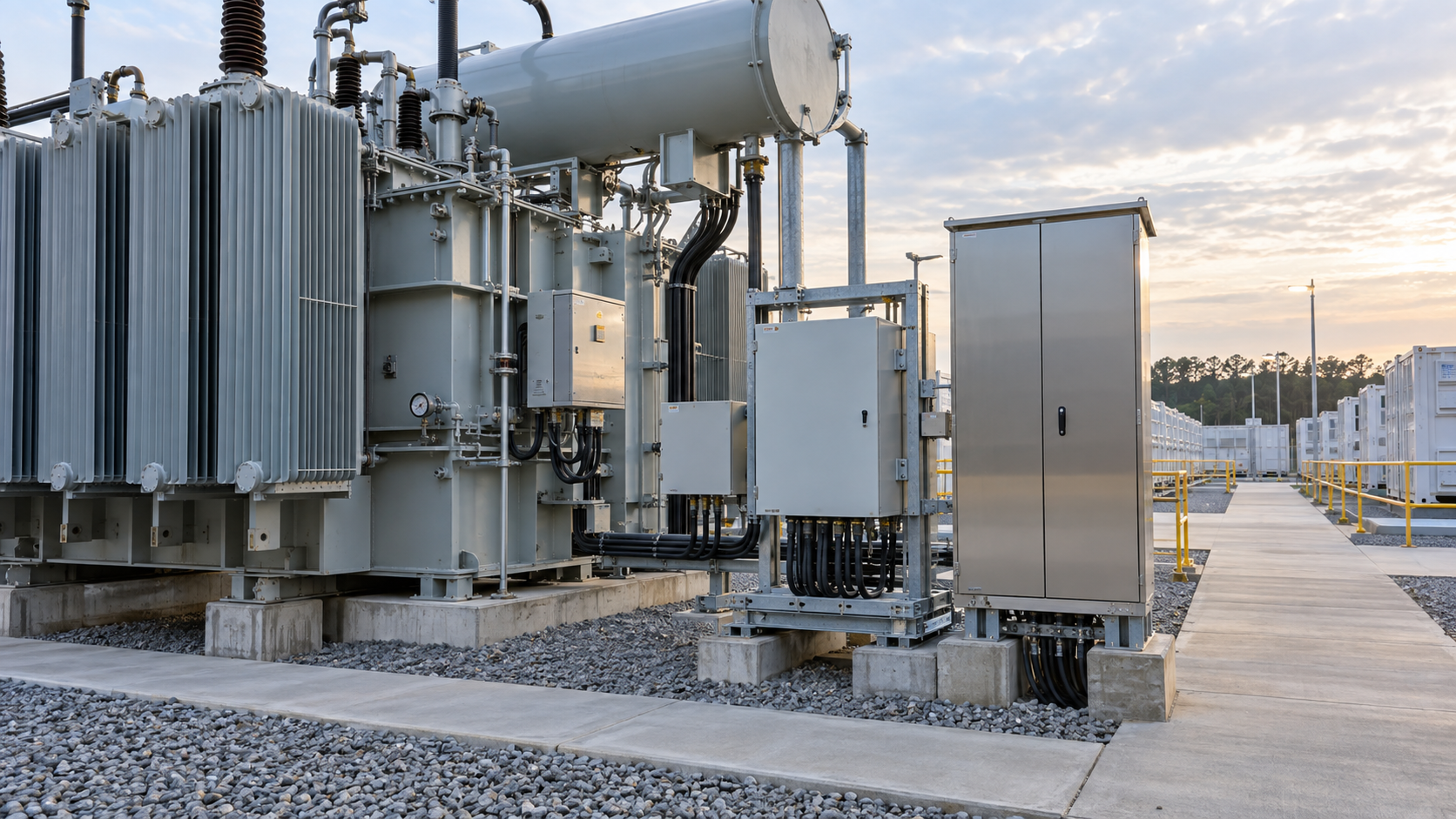
High ambient temperature reduces the difference between transformer surface temperature and surrounding air, which can reduce cooling margin. Dust accumulation can also obstruct radiator surfaces or filters in enclosed equipment. These effects should be addressed through the project thermal study, radiator arrangement, fan staging, alarm settings, inspection access and cleaning plan.
For oil-immersed equipment, confirm the cooling designation, radiator layout, removable clearances, fan redundancy where specified and the effect of a failed fan group. If the transformer is inside a container or acoustic enclosure, provide the ventilation calculation and maximum inlet-air temperature. The nameplate ambient outside the enclosure may not represent the air actually entering the coolers.
Maintenance access deserves an early layout check. Technicians need safe space for valves, sampling points, temperature devices, marshalling cabinets, cable terminations and any tap-changing equipment. A compact arrangement that cannot be inspected or cleaned without shutting down adjacent blocks may undermine availability.
Protection, Earthing and Control Interfaces
A complete protection concept normally coordinates transformer differential protection, overcurrent and earth-fault functions, winding and oil temperature, pressure devices, gas protection where applicable, breaker failure, intertrips and converter blocking signals. The exact scheme is project-specific. The tender package should include the protection single-line, CT data and a cause-and-effect matrix.
Confirm the earthing arrangement in every operating state. If a transformer neutral is brought out, state the neutral insulation level, grounding equipment, current rating and protection CT location. If a delta winding is used, identify how zero-sequence requirements are met elsewhere in the system. The transformer, switchgear and protection drawings must show the same boundary.
Control wiring should define signal voltage, terminal allocation, protocol, time synchronization and responsibility for the interface gateway. A long list of optional monitoring devices is not a substitute for an approved signal schedule. Select information that supports protection, condition assessment and operational decisions.
Plan FAT Around Evidence Needed for Site Release
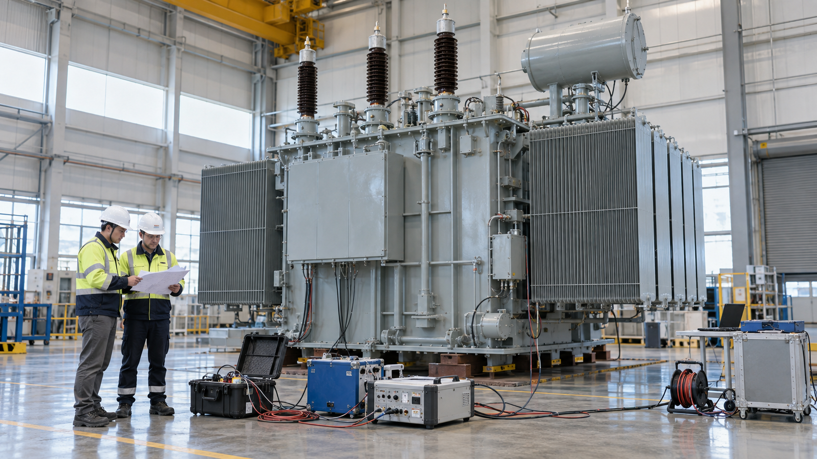
Factory acceptance testing should verify the transformer against the approved specification and design documents. The inspection and test plan can include routine electrical tests, ratio and phase displacement, impedance and loss measurements, insulation checks, accessory operation, alarm and trip contacts, cooling controls, marshalling wiring and tap-changer functions as contractually applicable.
Separate transformer FAT from integrated plant tests
The FAT should not be described as proof of the complete BESS plant. Converter controls, plant controller logic, grid protection and integrated operating sequences generally require site or system-level testing. The project should distinguish transformer FAT evidence from integrated commissioning evidence.
Record measured results, instrument identification, test configuration, acceptance criteria and outstanding actions. Use a release register so that open documentation items, shipping preparations and site verification steps are not lost after the factory inspection.
Procurement Checklist for a Reviewable Offer
Issue a single data schedule that separates required values, supplier guarantees and comments. Include rated power in each direction, voltage ratio, frequency, vector group, tap range, impedance, loss evaluation, cooling, ambient conditions, altitude, harmonic spectrum, insulation requirements, terminal arrangement, cable data, neutral equipment, monitoring, accessories, dimensions, mass and transport limits.
Ask for a compliance matrix with explicit deviations. A statement of “complies” is not sufficient when the proposal changes the cooling arrangement, tap range, bushing location or guaranteed loss basis. Require updated general arrangement, foundation loads, cable-box drawings, control schematics and document schedule before design release.
For related regional planning, review the 33 kV Gulf industrial transformer procurement guide and the Middle East dry-type transformer installation requirements. The transformer voltage-regulation guide explains additional study inputs that also matter when converters operate across a wide voltage range.
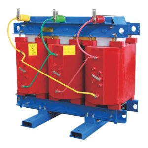
Product references include Zisheng Electric oil-immersed transformers, substation transformer solutions and dry-type transformers. These are product families; the appropriate construction and rating must be confirmed against the project-specific duty.
Information to Send Zisheng Electric
A reliable BESS transformer for Middle East projects is selected from an agreed operating envelope rather than a single MW figure. Send the drawings, transformer data sheet, load list, technical specification, single-line diagram, grid parameters, converter data, P-Q capability, harmonic spectrum, protection philosophy, environmental design basis, transport restrictions and installation-site conditions. Mark provisional values and identify when final data will be issued.
Zisheng Electric can review oil-immersed, dry-type and substation transformer configurations against the confirmed electrical and site interfaces. “Our engineering team will review the requirements and respond to project inquiries within 24 hours.”
About ZISHENG ELECTRICAL
Zisheng are a professional 19+ years manufacturer in producing Oil-Immersed Transformers, Compact Substation, Pad Mounted Transformers, Pole Mounted Transformers and Dry Type Transformers. We own the certificates of ISO/CE/IEC 60076 and TUV Rheinland.
Transformers undergo rigorous FAT and type testing, support voltage/capacity customization. Welcome to consult for Catalog and Product. you can contact us at email [email protected].