مؤشر درجة حرارة لفات المحولات للمشاريع الصناعية الأفريقية: أجهزة الاستشعار، ووحدات التوصيل، ونظام SCADA
Zisheng Electric often sees the same gap in an industrial transformer inquiry: the rating, impedance and cooling class are defined, while the temperature instruments are left as a short accessory line. A transformer winding temperature indicator then becomes an interface problem at the worst point in the project. The transformer supplier may provide a dial and contacts, the protection contractor may expect a trip signal, and the plant control team may expect a continuous value in SCADA. Each party can be working to a different assumption.
For African industrial projects, the right specification begins with the operating decision the signal must support. A cement line, mine concentrator or water plant may have variable loading, motor starts, a remote control room and limited access to specialist spares. None of those conditions gives a universal alarm temperature. They do determine which measurements, contacts, wiring drawings and acceptance checks need to be agreed before manufacture.
What a transformer winding temperature indicator actually indicates
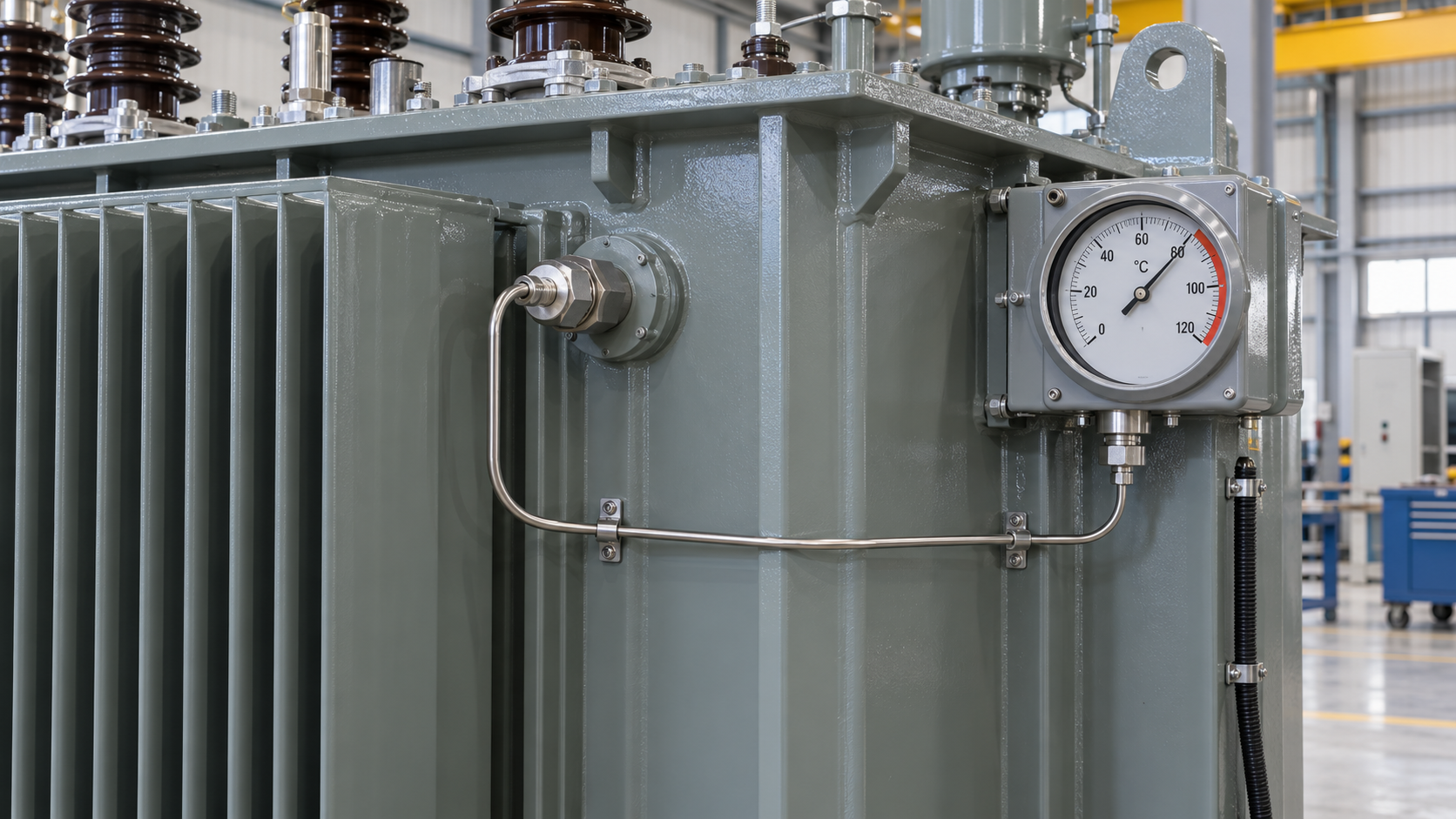
An oil temperature indicator measures temperature at its installed sensing point, commonly a pocket associated with top oil. A conventional winding temperature indicator often adds a current-dependent heating element to an oil-temperature sensing arrangement. This produces a thermal image of winding temperature rather than a direct measurement at the conductor hot spot. The current input, matching unit, sensor location and calibration matter because a visually plausible dial can still represent the wrong winding or the wrong load current.
Direct fiber-optic winding sensors are a different architecture. They may be selected for a specific design and monitoring objective, but their presence must never be inferred from the words “winding temperature indicator.” The tender should identify whether it requires a simulated winding indication, a direct sensor system, or both. The purchaser should also state whether the displayed value is for local observation, cooling control, alarm, trip, trend analysis or a combination. These are distinct functions with distinct failure consequences.
The IEC 60076-7:2018 loading guide addresses mineral-oil-immersed transformer loading from the perspective of operating temperatures and thermal ageing. It is a useful technical reference for reviewing the thermal basis, but it does not replace project-specific setpoints, protection coordination or the manufacturer’s instrument data. In particular, avoid lifting an alarm number from another installation without checking the offered winding design, cooling stages and load profile.
Specify the transformer winding temperature indicator as an interface package
The minimum useful inquiry is more detailed than “WTI with alarm and trip.” It identifies the monitored winding, CT source, control supply, output type, quantity of contacts, intended consumers, location of the instrument and the tests that will prove the assembled circuit. If more than one winding or cooling stage needs independent control, say so. Otherwise a supplier may offer a technically sound single-channel unit that cannot serve the operating philosophy.
| بند القرار | Information to freeze | Why it matters to procurement and commissioning |
|---|---|---|
| Indication principle | Top-oil, simulated winding, direct winding or combined monitoring | Prevents unlike quotations from being treated as equivalent |
| Current input | Source CT, ratio, burden allowance and monitored winding | Incorrect input can make the thermal image unrepresentative |
| Contacts | Separate duties for fan start, alarm, trip and spare; contact form and rating | A single contact cannot silently serve several owners |
| Remote output | Required analog or digital interface, scale, supply and loss-of-signal behavior | SCADA point lists and panels can be designed before arrival |
| Setpoints | Approval owner, adjustable range, deadband and recorded final values | Reduces nuisance operation and undocumented field changes |
| الأدلة | Instrument datasheet, wiring diagram, calibration record, FAT and site test sheets | Allows a purchaser to accept a functioning system, not a mounted dial |
This table is a bid comparison tool, not a claim that every project needs every output. A naturally cooled distribution transformer may have a simpler arrangement than a large forced-air power transformer. The buyer should delete functions that are not required and keep an explicit record of the remaining interfaces. That produces clearer bids and fewer changes during panel integration.
Separate oil indication, winding simulation and protection logic
It is easy to confuse the physical measurement with the action taken from it. The top-oil sensor tells the operator what the oil is doing at the sensing pocket. A simulated winding channel adds a load-related rise. A protection relay or control panel decides what to do when a contact changes state. The transformer purchase order should state which equipment owns each step.
For example, a plant may want local fan control at the transformer, a remote high-temperature alarm at the control room and a high-high condition routed through the protection system. The wiring drawing must show whether contacts are normally open or normally closed in the defined healthy state, which terminal numbers belong to each function and what happens if auxiliary power disappears. Do not rely on the label “alarm contact” alone. A dry contact has no meaning until the receiving circuit and its supervision method are defined.
If the project uses a continuous remote value, document the transmitter range, signal type and source of power. A displayed local temperature and a SCADA value should be compared during commissioning at known test points. The control team also needs to know whether a failed sensor, open loop or lost supply gives an out-of-range value, a fault flag or a frozen reading. A trend that looks stable during a broken signal is operationally worse than an obvious alarm.
Cooling logic deserves its own review. Fan start and stop points, hysteresis, manual override, duty rotation and alarm on fan failure belong in the approved control philosophy. The temperature indicator may provide contact inputs, while the marshalling cabinet or plant control system performs the sequencing. Where forced cooling is offered, the buyer should reconcile the thermal design with the actual auxiliary power arrangement. Our transformer auxiliary power specification guide explains why controls and fan supplies should be checked before energization.

Match the instrument to the site and maintenance model
African industrial sites are not a single environmental category. One project may be on a hot inland plateau; another may face coastal humidity; a third may have process dust and frequent cleaning. Ask for the site design basis rather than a generic regional rating. Include the specified ambient profile, enclosure location, direct sun exposure, washing practice, corrosive atmosphere if applicable, transport route and expected maintenance access. The supplier can then propose an instrument housing, cable glands, capillary routing and terminal protection suitable for that actual installation.
Mount the dial where an operator can read it without reaching across energized connections or climbing onto pipework. Protect capillary tubes and sensor leads from transport damage, sharp bends and maintenance traffic. If a sensor pocket is removable, the operating procedure should explain isolation, sealing and replacement. A design that is serviceable in the factory may become inaccessible when radiators, cable boxes, walls and fire barriers are installed around it.
Spare planning is part of the same decision. Record the instrument model, sensing element, contact configuration, terminal arrangement and any matching unit rather than ordering a generic “temperature gauge.” If the site keeps one spare, confirm that it can be fitted and calibrated without changing the protection logic. For remote plants, the time needed to import a small proprietary device can be more consequential than its purchase price.
For a broader thermal design review, our tropical mining transformer cooling guide covers load profiles, airflow, dust and maintenance access. The present article addresses the measurement and control interface that allows operators to see whether that cooling design is behaving as intended.
Turn setpoints into an approved operating decision
Alarm and trip values are often copied into a bid schedule before the transformer design and plant operating philosophy are available. That can create either nuisance trips or false comfort. A sound process begins with the manufacturer’s thermal design data, cooling configuration, intended loading, ambient basis and any overload study. The owner and protection engineer then decide what action is needed at each threshold. The selected values should be reviewed against the instrument’s accuracy, switching differential and available range.
Keep a setpoint register with the signal name, action, initial proposed value, approval authority, final setting and test evidence. If the control system adds a delay or voting logic, record it separately from the temperature switch. A factory test of the switch does not by itself prove the plant trip path. Likewise, a successful relay injection does not establish that the temperature sensor is correctly installed. Both ends of the chain need evidence.
Do not use a temperature indication as a substitute for protection coordination. The appropriate role of a high-temperature trip depends on the transformer, process criticality, redundancy and operating rules. On a continuous-process plant, the owner may require staged alarms and controlled load reduction before a final trip. On another installation, a faster trip may be required. That is a project decision, not a universal product feature.
Plan a FAT that proves the complete signal path
The factory acceptance test should identify what can be demonstrated on the completed transformer and what must wait for site integration. A useful FAT starts with instrument identification: compare the installed model and serial number with the approved datasheet and drawings. Check physical mounting, sensor pocket, capillary support, terminal seals and nameplates. Then verify each contact function at a controlled stimulus, record the actuation and reset points, and compare them with the approved settings and tolerances.
Prove the simulated winding input
For a simulated winding channel, the test plan should explain how its current input and heating compensation are checked. A simple warm-up of the oil sensing element may prove the dial moves, but it does not alone prove the CT source, ratio or thermal-image matching. Where full load simulation is impractical, document the separate checks and the limitation of each. The acceptance record should state the stimulus, instrument reading, contact state, terminal numbers and tester. “WTI OK” is not a useful handover record.
Prove the outgoing contacts and values
Loop checks should extend to the marshalling cabinet terminals and, when available, the purchaser’s witness interface. Verify analog outputs at multiple points and simulate sensor or supply failure where supported by the offered device. If fans are part of the package, demonstrate auto and manual modes, interlocks and feedback rather than only the fan motor rotation. Record any test bypasses, then show they have been removed before release.
The transformer fire protection interface guide discusses a similar handoff problem: a signal is useful only when its owner and downstream action are defined. Temperature contacts deserve the same clarity in the cause-and-effect schedule.

Close the site commissioning and handover gap
Shipping, installation and site wiring can change a system that passed FAT. During receipt inspection, check the instrument face, capillary route, enclosure seals and terminal box for damage or moisture. Compare the installed CT secondary wiring with the released schematic; do not open a live CT secondary to “see if the gauge changes.” Before energization, confirm terminal continuity and insulation checks using the instrument manufacturer’s limits and the approved commissioning method.
During a controlled first loading period, compare local oil and winding indications with remote values, load current, ambient conditions and cooling stage. A disagreement is a prompt to investigate signal scaling, CT input and sensor installation before adjusting setpoints. Record the as-left settings and the person who approved them. The plant operator should receive a concise alarm response sheet that distinguishes a high reading, a failed instrument and a failed fan.
For an EPC contractor, the deliverable is a traceable chain from inquiry specification to instrument datasheet, transformer drawings, FAT sheet, loop test and as-left register. For a distributor, it is also a repeatable spare definition. For the owner, it is confidence that an operator can understand and act on the signal during a real event.
Procurement checklist for a transformer winding temperature indicator
Before placing the order, request a marked-up instrument schedule with the measurement principle, monitored winding, current source, local display, contact assignments, remote signals and environmental details. Add the control philosophy and cause-and-effect matrix as controlled references. Require supplier comments on any missing CT information, panel supply, cable route or communication interface. A clean deviation list is more valuable than a bid that silently assumes all gaps can be settled at site.
Zisheng Electric can review these interfaces alongside the transformer design. The relevant 66 kV oil-immersed power transformer و محول طاقة 132 كيلوفولت/138 كيلوفولت product pages provide starting points for discussing a project-specific package; neither page should be taken as a promise that every instrument option is standard. Send drawings, datasheets, load lists, technical specifications, the single-line diagram, grid parameters, environmental conditions and installation-site constraints. A complete transformer winding temperature indicator schedule lets our engineers resolve the sensor, contacts and handover evidence with the same discipline as the main electrical ratings. Our engineering team will review the requirements and respond to project inquiries within 24 hours.
عن شركة ZISHENG ELECTRICAL
زيشينغ هي شركة متخصصة ذات خبرة تمتد لأكثر من 19 عاماً في التصنيع والإنتاج المحوّلات المغمورة بالزيت, المحطات الفرعية المدمجة, المحوّلات المركبة على القواعد, المحوّلات المثبتة على الأعمدة و المحوّلات الجافة. نحن نمتلك شهادات ISO/CE/IEC 60076 وTUV Rheinland.
تخضع المحولات لاختبارات FAT واختبار المواصفات النوعية بشكل صارم، وتدعم تخصيص الجهد/السعة. نرحب باستشارتكم بشأن كتالوج و المنتج. يمكنك الاتصال بنا عبر البريد الإلكتروني [email protected].