Transformer Neutral Grounding Resistor Interface for African Industrial Projects: Fault Current, CT Location and Protection Coordination
For an industrial project, the transformer neutral connection can look like a small interface on the single-line diagram. In practice, it determines how a ground fault is limited, detected, cleared and recorded. Zisheng Electric therefore treats the transformer neutral grounding resistor interface as a coordinated design package rather than a loose accessory. The transformer, neutral grounding resistor (NGR), current transformer, relay logic, cables, earthing grid and site operating philosophy must all describe the same system.
This coordination is especially important for EPC contractors and industrial owners working across African markets. A project may combine an imported transformer, locally supplied switchgear, a protection panel from another vendor and an earthing design prepared by the EPC team. If their interface data are incomplete, the equipment may still arrive on time but commissioning can stop at the first earth-fault injection test. The correct procurement approach is to fix the design basis, allocate responsibility and require evidence before manufacturing release.
Why the Transformer Neutral Grounding Resistor Interface Matters
An NGR introduces intentional resistance between a transformer neutral and earth. Its purpose is to control earth-fault current so that damage, touch-voltage risk and protection performance can be managed as a system. It is not simply a resistor with a voltage rating. The selected current and time rating influence winding thermal stress, cable damage, relay sensitivity, fault duration and the operational decision to trip immediately or continue temporarily under controlled conditions.
The interface begins with the transformer winding connection. A star-connected winding may provide an accessible neutral, while a delta system may require a separate earthing transformer if the project philosophy calls for resistance grounding. The neutral terminal must have an insulation level, mechanical arrangement and short-time current capability compatible with the final scheme. The EPC team should not assume that a neutral bushing shown on a general arrangement drawing automatically includes the cable box, link, CT, surge protection, support steel or NGR connection cable.
Public technical guidance from Eaton on power-system grounding techniques explains how resistance grounding changes the magnitude and behavior of ground-fault current. ABB also documents how earth-fault protection applicability varies with the chosen neutral earthing principle. These sources reinforce a practical procurement point: the resistor and the relay settings cannot be specified independently.
Freeze the Grounding Philosophy Before Requesting a Transformer Bid
The first engineering decision is not the resistor ohmic value. It is the system operating philosophy. The owner must state whether a first earth fault requires immediate isolation, whether process continuity is expected, which sources can energize the bus and which protection device has final tripping authority. A mine, cement plant, water facility and data center may all use medium-voltage transformers, but their acceptable fault duration and continuity requirements are different.
Inputs the EPC team must provide
At inquiry stage, suppliers need the nominal system voltage and frequency, transformer vector group, winding neutral availability, maximum and minimum source configurations, earthing grid arrangement, expected cable lengths, relay types and the required clearing philosophy. Motor contribution, generator operation and parallel transformer modes must be included where they affect zero-sequence behavior. If a standby generator can energize the same bus, the grounding path in generator mode must be shown rather than left for commissioning.
The project should also define ambient temperature, altitude, enclosure location, ingress protection, corrosion class, ventilation, cable-entry direction and space for inspection. These items change the NGR enclosure design and resistor temperature rise. The electrical duty may be correct while the physical assembly is still unsuitable for a dusty outdoor substation or a coastal industrial site.

Transformer Neutral Grounding Resistor Interface Decision Table
| بند القرار | Required project input | Supplier evidence | Risk if unresolved |
|---|---|---|---|
| Ground-fault current | System study and operating philosophy | Rated current, resistance tolerance and design calculation | Relay insensitivity or excessive fault damage |
| Duty duration | Protection clearing time and permitted operating mode | Short-time or continuous thermal rating | Resistor overheating before isolation |
| Neutral insulation | Transformer neutral insulation basis and switching conditions | Neutral terminal and NGR insulation data | Insulation mismatch at the interface |
| Neutral CT location | Protection philosophy and physical single-line diagram | CT ratio, class, burden and installation drawing | Incorrect measurement or blind protection zone |
| Cable and termination | Route length, conductor size, entry direction and gland standard | Terminal dimensions, gland plate and support details | Late site modification or unsafe bend radius |
| Monitoring and alarms | SCADA points, relay logic and local indication | Wiring diagrams, terminal schedule and cause-and-effect matrix | Fault not annunciated or wrong trip command |
| Earthing connection | Site grid conductor and bonding philosophy | Earth terminals and bonding drawing | Uncontrolled return path or unsafe touch potential |
| Environmental design | Temperature, altitude, dust, humidity and corrosion exposure | Enclosure material, IP provision and derating statement | Premature deterioration or thermal failure |
This table should become part of the technical bid evaluation. A supplier response of “by others” is acceptable only when the boundary is explicit and another party has acknowledged the duty. The aim is not to force every component into the transformer supply. It is to prevent an unowned gap between packages.

Select Fault Current and Time Rating as a Protection Package
The current selected for resistance grounding must be high enough for dependable detection under the worst credible operating condition, yet low enough to achieve the intended reduction in equipment damage. There is no universal value that can be copied between projects. System charging current, voltage, equipment insulation, process continuity, protection sensitivity and permitted fault duration all matter. Values should come from the approved grounding and protection studies, not from a catalog default.
The time rating requires the same discipline. A relay may have a nominal fast trip, but breaker opening time, backup protection and failed-breaker logic extend the thermal duty. Maintenance modes and commissioning tests can also expose the resistor longer than expected. The purchaser should define the required duration and ask the NGR supplier to confirm the thermal basis, permissible temperature rise and recovery conditions.
Transformer impedance is relevant to phase faults, but it does not replace the zero-sequence network model needed for earth-fault coordination. The study must represent the winding connections, source availability, earthing transformer where used, cable capacitance and all intentional grounding points. This is why the technical deviation register should flag any change to vector group, neutral access, CT data or grounding duty before purchase-order release.
Define the Neutral CT Location and Protection Boundary
A neutral CT can provide sensitive measurement of current in the grounding connection. Its location must be shown on both the single-line diagram and the physical arrangement. Placing the CT between the transformer neutral and the NGR is not equivalent to placing it on another earth path. The drawing must identify whether the CT encloses one conductor, where screen and earth connections pass, and which faults lie inside the protected zone.
Ratio, class, burden and knee-point requirements depend on the selected protection method and relay. The cable length between CT and relay contributes burden. Terminal blocks, test switches and shorting facilities must support safe injection testing. A CT data sheet without a complete secondary-circuit burden is not enough for final selection. For a broader procurement treatment, Zisheng Electric’s guide to transformer protection CT specification explains how ratio and burden evidence should be reviewed.
Protection coordination should also define alarms, trip outputs, lockout, breaker-failure initiation and SCADA indication. If multiple transformers can operate in parallel, each grounding point and CT must be modeled in every permitted switching state. Otherwise parallel operation can change the fault-current split and invalidate a setting that worked with one transformer in service.
Control Multiple Grounding Paths and Parallel Sources
Unintended parallel neutral-to-earth paths are a frequent commissioning problem. They may be introduced through a generator neutral, station-service transformer, cable screen, switchboard bond or temporary construction connection. The result can be circulating current, incorrect CT measurement or a fault-current path that bypasses the NGR. A marked-up grounding diagram is therefore as important as the main single-line diagram.
For two transformers operating in parallel, the owner must state whether both neutrals remain grounded, one grounding point is selected, or switching interlocks control the arrangement. The study must examine normal, maintenance and transfer conditions. It should also confirm that no prohibited operating state can occur during automatic transfer. This review belongs alongside the transformer’s impedance and vector-group checks, not after delivery.
Other interface equipment can influence the same study. Surge arresters, capacitor banks, cable screens and metering circuits have separate functions, but their earth connections share the site grid. The articles on surge arrester coordination و transformer metering interface provide useful companion checks when the EPC team freezes the complete substation arrangement.
Allocate Supply Boundaries on Drawings and Schedules
The purchase specification should include a boundary schedule for the transformer supplier, NGR supplier, switchgear supplier and EPC contractor. Typical line items include neutral bushing, removable link, neutral CT, cable, support structure, glands, surge protection, resistor enclosure, space heater, marshalling terminals, local indicators, earth bars and inter-package wiring. Each line needs a design, supply, installation and test owner.
Physical information must be exchanged early. The NGR location affects cable length, voltage drop, mechanical support and access for inspection. A route that crosses hot surfaces or congested trenches can create installation risk. If the NGR is mounted near the transformer, the layout must preserve transformer maintenance clearances, radiator airflow, oil sampling access and safe escape routes.
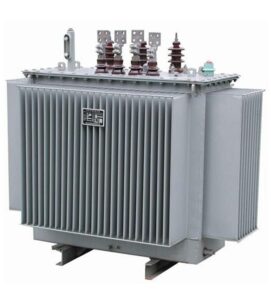
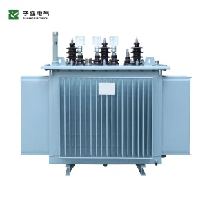
Zisheng Electric can coordinate this interface around an محوّل مغموس في الزيت or a packaged محول المحطة الفرعية. The final scope should still be project-specific: product selection does not replace an approved grounding study or site earthing design.
FAT, Site Tests and Handover Evidence
Factory testing should verify the components that are actually within the supplier’s scope. Useful records include resistor resistance at a stated temperature, insulation checks, CT polarity and ratio evidence, terminal identification, wiring continuity, alarm operation and enclosure inspection. If the complete system cannot be assembled at the factory, the FAT procedure should distinguish tested functions from simulations and list the remaining site tests.
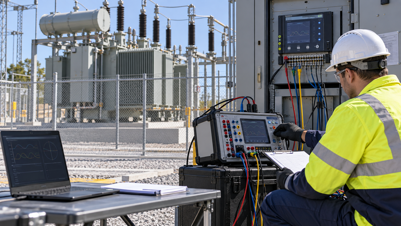
At site, the team should confirm cable routing, terminations, earth bonding, CT orientation, secondary continuity and relay settings against approved drawings. Primary or secondary injection should prove the intended alarm and trip sequence without assuming that a changing relay indication is enough. The cause-and-effect record should identify the breaker, lockout relay, SCADA point and reset method. Resistance measurements should be compared with factory data after temperature correction where required by the approved procedure.
The handover package should contain the as-built single-line diagram, grounding diagram, protection settings, CT schedule, NGR data sheet, test reports, wiring drawings, terminal schedules, spare-parts list and operating instructions. These records matter because later plant expansion or generator addition can change the zero-sequence network. Without a controlled baseline, the next modification begins with assumptions.
Procurement Checklist for EPC and Industrial Buyers
Before technical bid closure, confirm that the transformer neutral terminal is available and rated for the intended connection; the grounding method is approved; fault current and duration are stated; the neutral CT is located and specified; all permitted source configurations are studied; cable and earth interfaces are dimensioned; environmental conditions are declared; and monitoring points are included in the I/O list. Open items should have named owners and due dates.
Before manufacturing release, compare the transformer’s general arrangement, NGR drawing, protection single-line and site layout on one coordinated review. Before shipment, close FAT deviations and verify that loose items, links, CT accessories and terminal hardware are identified in the packing list. Before energization, review the approved relay settings and as-built grounding path with the commissioning team.
Build a Verifiable Transformer Neutral Grounding Resistor Interface
A dependable transformer neutral grounding resistor interface is the result of coordinated system decisions, not a late accessory selection. Zisheng Electric can review transformer neutral arrangements, protection-CT requirements, terminal interfaces and equipment layout as part of a project-specific transformer or substation package.
For an engineering review, provide the drawings, data sheets, load list, technical specification, single-line diagram, grid parameters, environmental conditions and installation-site conditions. Include the grounding study, protection philosophy, source operating modes, CT and relay data, earthing layout and required fault duration where available. Our engineering team will review the requirements and respond to project inquiries within 24 hours.
عن شركة ZISHENG ELECTRICAL
زيشينغ هي شركة متخصصة ذات خبرة تمتد لأكثر من 19 عاماً في التصنيع والإنتاج المحوّلات المغمورة بالزيت, المحطات الفرعية المدمجة, المحوّلات المركبة على القواعد, المحوّلات المثبتة على الأعمدة و المحوّلات الجافة. نحن نمتلك شهادات ISO/CE/IEC 60076 وTUV Rheinland.
تخضع المحولات لاختبارات FAT واختبار المواصفات النوعية بشكل صارم، وتدعم تخصيص الجهد/السعة. نرحب باستشارتكم بشأن كتالوج و المنتج. يمكنك الاتصال بنا عبر البريد الإلكتروني [email protected].