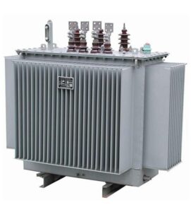
Transformer Seismic Anchorage for Chilean Industrial Projects: Foundation, Connections and Acceptance
Zisheng Electric asks industrial buyers in Chile to treat transformer seismic anchorage as a coordinated equipment and civil-design interface. A transformer may meet its electrical specification yet arrive with a support footprint, centre of gravity or accessory arrangement that the approved foundation was never designed to resist. The purchase order should make the seismic basis, responsibility for calculations and required vendor data visible before equipment and concrete are committed.
This is a solutions guide for a hypothetical industrial expansion, not a claim about a delivered Chilean project. The actual hazard, soil response, design category, applicable regulation and acceptance method must be established by the project’s licensed designers and owner. Chile’s National Energy Commission has published a technical annex for seismic requirements for high-voltage electrical installations; its applicability to the particular facility and contract should be confirmed in the design basis. No universal acceleration, anchor spacing or qualification certificate is implied here.
Set the seismic basis before choosing a transformer foundation
Begin with the utility connection and single-line diagram, then locate the transformer on the civil general arrangement. Record coordinates, operating elevation, soil and foundation information, equipment importance to the process, and whether the installation is a new bay or a replacement on an existing plinth. The structural designer should provide the governing seismic design actions and the allowable support movement or drift at connected equipment. This turns a vague phrase such as “seismic suitable” into a set of design inputs that the supplier can answer.
Chile’s National Energy Commission notice on high-voltage installation seismic requirements is a useful official starting point. The project team must identify the current annex, any industrial structural standard used in the contract, utility conditions and local approval path. Different facilities can adopt different design cases. Ask the civil engineer to state the exact documents and revision dates rather than simply writing “Chile code”.
Build a transformer seismic anchorage interface schedule
The transformer supplier knows the equipment geometry, masses and support points. The civil engineer knows the foundation and design action. The EPC contractor should combine them into one controlled schedule with an owner for each dimension and calculation. Include the main tank, detachable radiator banks, conservator, cable box, marshalling kiosk, bushings and other equipment whose mass or restraint can affect the support system.
| Interface item | Information to obtain | Design decision | Acceptance evidence |
|---|---|---|---|
| Main unit support | Operating, shipping and lifting masses; centre of gravity; foot or wheel geometry | Support reactions and anchorage arrangement | Approved general arrangement and structural calculation |
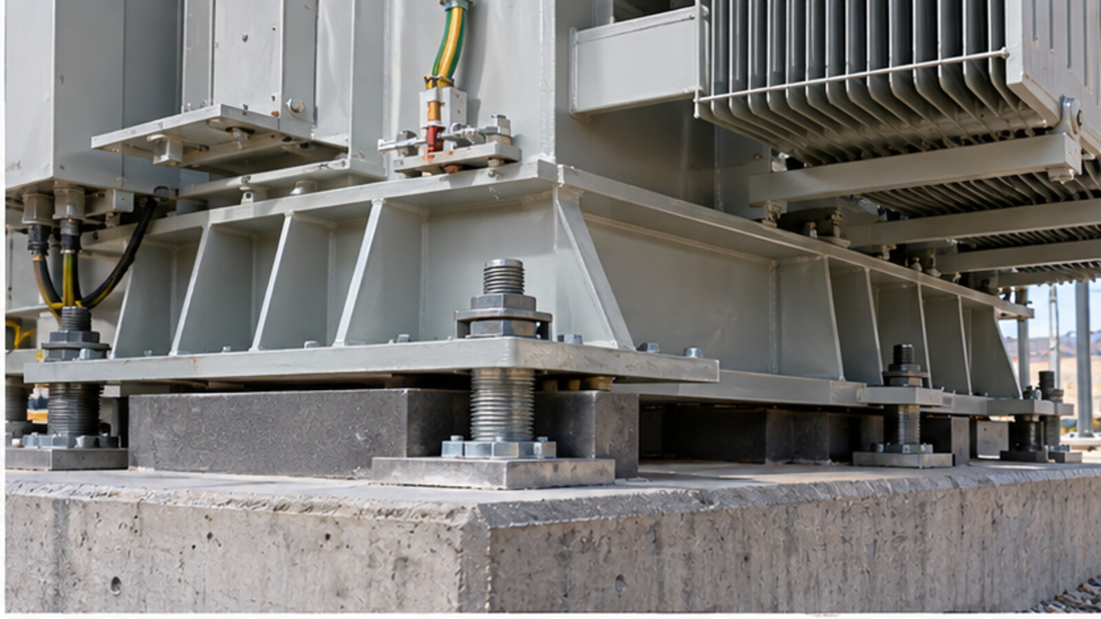
| Anchor connection | Base-plate holes, edge distances, fastener access and construction tolerance | Anchor type, embedment and installation sequence | Approved detail, inspection and installation record |
| Detachable accessories | Separate masses, attachment details and shipping condition | Local bracing and site reassembly check | Supplier drawing and signed assembly record |
| Electrical connections | Terminal coordinates, movement envelope, cable or bus properties | Allowable displacement and connection flexibility | Interface drawing and field fit inspection |
| Existing foundation | As-built dimensions, condition, reinforcement and geotechnical data | Reuse, strengthening or replacement | Civil survey and engineer’s disposition |
| Post-event access | Valves, drains, jacking points, isolation and inspection routes | Maintainability under the proposed layout | Coordinated equipment and site layout |
The schedule is deliberately qualitative. The responsible structural designer must insert project-specific numerical actions, load combinations and acceptance limits. Procurement can then compare two offers using the same basis rather than a vendor’s unsupported statement that a unit is “earthquake proof”.
Check the mass and support geometry as one assembly
A dry shipping mass may be lower than the operating mass with liquid, bushings and radiators installed. A centre-of-gravity estimate for transport can differ from the final installed assembly. Request both conditions and the principal component masses. If the design includes wheels, rails, skid beams or jacking pads, show whether they are part of the permanent restraint or only an installation aid.
A nominally similar replacement transformer can create different anchor reactions because its tank is longer, radiator banks are shifted, or its conservator sits higher. This is especially important during a short industrial shutdown, when civil changes may be difficult to complete. The site survey should measure the actual bolt pattern and foundation condition before manufacturing release. Zisheng Electric’s Chile transformer replacement checklist covers the wider outage and interface review; here the focus is on structural and restraint evidence.
Ask the supplier whether the stated reactions include wind, short-circuit mechanical loads or other operating actions where relevant to the project. The civil engineer should combine them using the approved design method. Avoid adding peak values from unrelated load cases without engineering review.

Protect bushings, coolers and connected conductors
Strong anchors do not guarantee a functional installation if relatively flexible accessories are overstressed. Identify the supports and bracing for coolers and conservator pipework. Check the bushing assembly, surge arresters, cable box and marshalling kiosk for relative motion with the main tank. The supplier should state any shipping braces to remove and any permanent restraints to retain after site assembly.
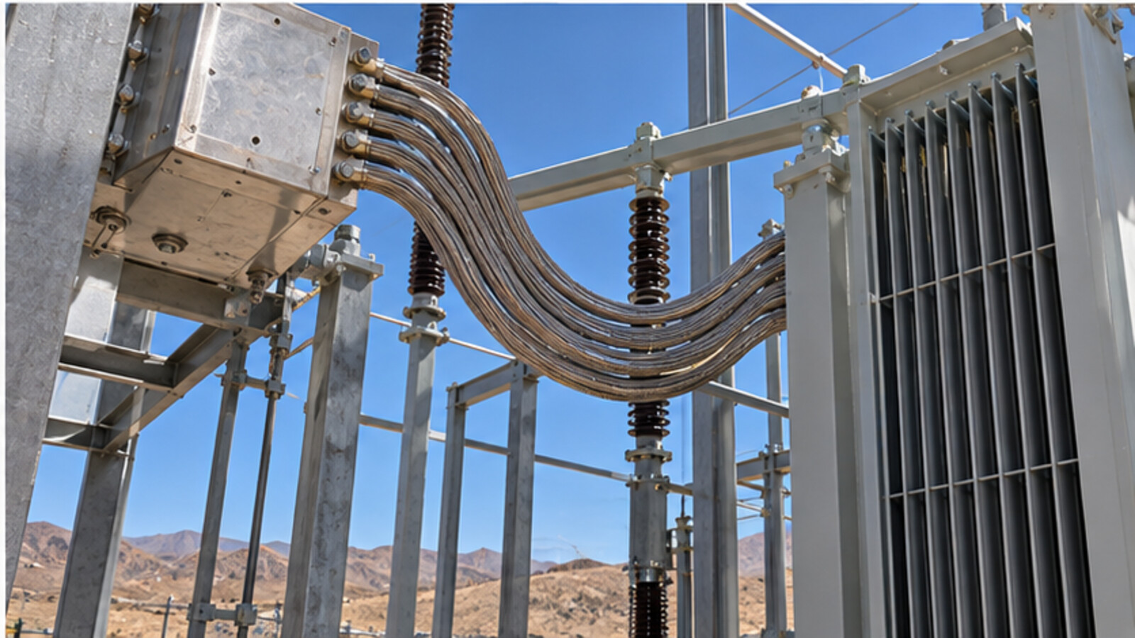
Rigid bus duct and short cable tails can transfer displacement into transformer terminals. The electrical designer should assess the compatible movement envelope, conductor flexibility, fault-force supports and required clearances at the actual connection. A deliberately flexible link still needs a defined continuous-current rating, short-circuit duty and fatigue or maintenance approach. Do not use an unverified long loop simply because it looks compliant in a photograph.
For a Chile industrial procurement package, the transformer replacement outage planning guide is a useful comparison for execution gates, while local structural and electrical requirements remain project-specific. The design should show the final position of cable trenches, fire walls, oil containment and access routes so restraint hardware does not block routine service.
Make anchor installation inspectable
The anchorage detail must be constructible with the transformer in place. Check bolt projection, wrench clearance, grout access, edge distance, reinforcement conflicts and permitted hole tolerances. The sequence for positioning, levelling, grouting, tightening and final inspection should be set before equipment arrives. If post-installed anchors are proposed, the structural designer must verify their suitability for the concrete condition, cracking assumption and project design action; the transformer supplier should not silently choose them on site.
Record anchor identity and batch, approved installation procedure, foundation strength or release evidence, as-built position, fastener condition and final inspection. A yellow paint witness mark alone does not prove embedment, tightening or the concrete beneath a base plate. Deviations should be referred back to the structural designer with a documented repair or concession, not corrected by elongating a hole in the transformer support without engineering approval.
Distinguish qualification from project acceptance
Ask vendors exactly what a test report or analysis demonstrates. Was it prepared for the offered configuration, mounting arrangement, accessory set and design input? A test on a smaller dry-type unit does not automatically qualify a larger oil-filled power transformer. IEC 60076-11:2018 includes a seismic class for dry-type transformers; that fact does not establish the class or acceptance method for this oil-immersed installation. The contract should specify the equipment-specific qualification route chosen by the owner and responsible engineers.
Electrical factory tests prove electrical characteristics under their stated conditions. They do not measure the completed site anchor embedment or all cable flexibility after erection. Separate the supplier’s manufacturing evidence, the civil design package and the site installation record. Verify that drawings and calculations have matching revision identifiers before accepting a package as closed.
Translate Chile site conditions into design inputs
Seismic design is one part of the Chilean site brief. Confirm the actual utility voltage and frequency at the connection, maximum and minimum ambient temperatures, altitude, humidity, dust, coastal salt exposure if applicable, rainfall, access route and lifting restrictions. A coastal yard and a high-elevation mine impose different insulation, coating, cooling and maintenance questions. The name of the country cannot resolve those values.
Where a site is remote, list the available crane capacity, road width, bridge limits and temporary laydown space. Shipping split decisions can change the installed mass distribution and create field-made oil joints. If the buyer wants a spare unit, define whether the same support geometry and terminal arrangement must be interchangeable, and whether the spare will be stored with bushings or radiators removed.
For electrical selection, the confirmed load schedule, motor-starting case, nonlinear loads and fault level still control transformer MVA, impedance, taps and protective interfaces. Structural restraint cannot be designed independently of a significant change in the transformer rating or footprint. Product options might include a 132/138 kV power transformer and, for an appropriately studied lower-voltage system, a 10 MVA 33/11 kV power transformer; these are categories to review, not a claim that either is automatically qualified for the site.
Close the interface before manufacturing release
At tender, request a preliminary mass and support schedule and price any seismic qualification as a defined deliverable. Before civil release, obtain a coordinated general arrangement and interface drawing. Before factory release, compare as-built support dimensions, accessory attachment and shipping braces with the approved revision. Before energization, close anchor inspections, grounding continuity, electrical connections, oil-system assembly and the commissioning punch list.
Prepare an after-event inspection plan
The operator should know what to inspect after a significant seismic event before returning a transformer to normal duty. The plan can identify foundation cracking, anchor displacement, oil leaks, shifted accessories, damaged bushings, pulled conductors, tank-to-grid bond integrity and protection alarms. It should define who isolates equipment, who reviews the structural condition and who authorizes electrical testing. An external walkdown alone cannot prove the internal condition of a transformer, while a satisfactory electrical test cannot excuse a visibly damaged foundation.
Record baseline photographs and as-built measurements during handover so post-event changes can be assessed against a known starting point. Keep spare anchors, gaskets and critical accessories in a controlled list where the site’s outage consequences justify them. The exact inspection and re-energization sequence must follow the owner’s emergency procedure and responsible engineers’ assessment.
If a late transformer design change moves the centre of gravity or support point, reopen the structural calculation. If the foundation design changes, reconfirm the vendor’s available installation tolerances. This two-way change control avoids the familiar situation in which each discipline believes the other has accepted a revision that was never sent to them.
For a decision on transformer seismic anchorage, send Zisheng Electric the drawings, data sheets, load list, technical specification, single-line diagram, grid parameters, site-specific environmental conditions and installation constraints. Include the civil design basis, soil information, proposed support geometry, required approval route and any owner seismic criteria. We can return equipment masses, support and accessory data for the responsible EPC designers to coordinate. Our engineering team will review the requirements and respond to project inquiries within 24 hours.
About ZISHENG ELECTRICAL
Zisheng are a professional 19+ years manufacturer in producing Oil-Immersed Transformers, Compact Substation, Pad Mounted Transformers, Pole Mounted Transformers and Dry Type Transformers. We own the certificates of ISO/CE/IEC 60076 and TUV Rheinland.
Transformers undergo rigorous FAT and type testing, support voltage/capacity customization. Welcome to consult for Catalog and Product. you can contact us at email [email protected].