How to Select Transformer Capacity? A Guide to Load Calculation and Selection for 50 kVA to 5000 kVA Transformers
Zisheng Electric specializes in the R&D, manufacturing, and project services of transformers and power equipment. Its product range covers oil-immersed transformers, dry-type transformers, amorphous alloy transformers, and related power equipment. The company designs and manufactures products according to international standards such as IEC 60076 and GOST, and provides customized solutions based on different national grid conditions, industrial project requirements, and special operating environments. Its products and services are widely applied in power engineering projects across the Middle East, South America, Africa, Russia, and other markets.
Through long-term project experience, Zisheng Electric has participated in transformer selection and supporting solution design for various fields, including industrial plants, energy projects, commercial buildings, and infrastructure facilities. The company has accumulated extensive experience in transformer capacity matching. In actual projects, capacity selection directly affects equipment investment, operating efficiency, and power supply reliability.
If the transformer capacity is oversized, the initial investment will increase, and no-load losses will also rise, resulting in higher long-term operating costs. If the capacity is undersized, problems such as insufficient load capacity, frequent tripping, difficulties in equipment startup, and even transformer overheating damage may occur.
The rated capacity of a transformer is usually expressed in kVA, which represents apparent power, rather than directly equal to active power in kW. The difference between the two mainly depends on the power factor. For example, a 100kVA transformer can actually support approximately 80kW of active load when the power factor is 0.8. If the power supply mainly serves inductive loads such as motors, compressors, pumps, or variable frequency drive equipment, additional capacity margin is required because these devices generate several times the rated current during startup.
Therefore, transformer capacity selection cannot simply be based on adding up equipment nameplate power, nor should it blindly pursue “larger capacity is safer.” In actual engineering design, factors such as load type, load diversity factor, power factor, starting current, ambient temperature, future expansion requirements, and reliability requirements need to be considered comprehensively.
This article will systematically introduce how to properly select transformer capacity from commonly used capacity ranges of 50kVA to 5000kVA, covering load calculation methods, capacity matching principles, typical application scenarios, and common selection mistakes. The aim is to help engineering designers, EPC contractors, and end users improve selection accuracy and reduce project operating costs.
I. Standard Transformer Capacity Ratings
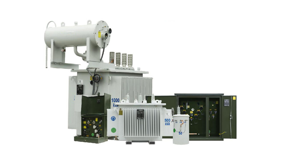
Domestic transformer rated capacities are arranged according to the R10 preferred number series. The R10 series means that the ratio between two adjacent capacities is the 10th root of 10, which is approximately 1.25. Each capacity level is obtained by multiplying the previous one by 1.25. Starting from 100kVA, the standard capacity sequence is: 100, 125, 160, 200, 250, 315, 400, 500, 630, 800, 1000… These values form the standard transformer capacity series.
Why not use smaller intervals? Because transformer manufacturing requires standardized molds and production processes. Too many specifications would increase manufacturing costs. This capacity series has been used in the industry for decades and is widely accepted.
Common transformer capacity ratings include:
Small capacity (50kVA-200kVA):
50, 80, 100, 125, 160, 200kVA
Medium capacity (250kVA-1000kVA):
250, 315, 400, 500, 630, 800, 1000kVA
Large capacity (1250kVA-5000kVA):
1250, 1600, 2000, 2500, 3150, 4000, 5000kVA
Transformers above 5000kVA usually belong to larger industrial and power system applications, involving more complex design and operating requirements. This article mainly discusses the common capacity range of distribution transformers.
One point worth mentioning: some customers ask whether a 700kVA transformer can be produced between 630kVA and 800kVA. In theory, customization is possible, but non-standard products usually have higher costs, longer delivery times, and more difficulties in future spare parts supply. Therefore, they are generally not recommended.
II. Factors Affecting Capacity Selection
2.1 Calculate the Load First, Then Determine the Capacity
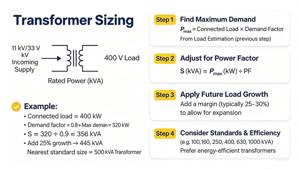
The first step in transformer selection is to determine the actual load demand. The nameplate power of all equipment cannot simply be added together, because equipment does not operate at full load simultaneously. The total load needs to be adjusted using the demand factor. Although this principle seems simple, incorrect calculations still frequently result in oversized or undersized transformers in actual projects. Many people skip detailed calculations for convenience and directly add all equipment ratings together, which often leads to unnecessary oversizing and increased investment costs.
Rough estimation:
Calculate the maximum load when all equipment operates simultaneously and reserve a 15%-20% capacity margin. This method is suitable for quick estimation during the early project stage.
Detailed calculation:
First calculate the load power of each phase, take the maximum phase load and multiply it by 3 to obtain the three-phase total power, then divide by the power factor (generally 0.8), and finally divide by the load factor (generally 0.85).
Example: In a building, the A-phase load is 10kW, the B-phase load is 9kW, and the C-phase load is 11kW. Take the maximum value of 11kW and multiply it by 3 to get 33kW. Divide by 0.8 to obtain 41.25kVA, then divide by 0.85 to obtain 48.5kVA. Select the next standard capacity level upward, so a 50kVA transformer is suitable.
Another example comparing two calculation methods:
| Calculation Method | Process | Result |
|---|---|---|
| Rough estimation | Total equipment nameplate power 75kW ÷ 0.8 ÷ 0.85 | Approximately 110kVA |
| Detailed calculation | Maximum demand calculated using load factor method: 40kW ÷ 0.8 ÷ 0.85 | Approximately 59kVA |
The difference between the two results is close to double, which creates a significant impact on project budget and long-term operating costs. For large projects, making a decision without detailed load calculations may result in unnecessary costs of hundreds of thousands or even millions.
2.2 What Load Rate Is Suitable
A transformer does not achieve the best performance when operating at full load. For a single transformer supplying stable loads, the load rate is generally designed at around 85%. In actual engineering applications, the economic operating load rate of ordinary distribution transformers is usually controlled between 60%-80%, depending on the load curve and operating cycle.
Why is higher load rate not always better? Because transformers have an “efficiency curve.” The optimal efficiency point is usually between 60%-80% load rate, rather than at 100%. When the load rate exceeds 80%, the growth rate of losses increases significantly.
A high load rate keeps the transformer operating close to overload conditions for a long time, accelerating insulation aging. A low load rate increases the proportion of no-load losses, making operation less economical. The 60%-80% range is generally considered the optimal operating range, providing higher efficiency and lower losses.
2.3 Differences Between Different Load Types
Resistive loads (lighting, electric heating equipment):
Capacity ≈ Load power ÷ power factor (take 0.9).
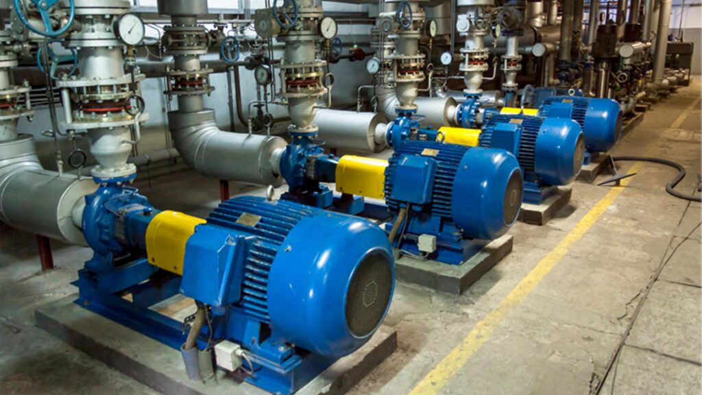
Inductive loads (motors, compressors, pumps):
Starting current is 2-5 times the rated current. Transformer capacity should generally be selected at 1.2-1.5 times the load power. For a 10kW motor, a transformer of 15kVA or above is recommended. If multiple large motors start simultaneously, additional capacity margin is required.
Non-linear loads (variable frequency drives, rectifiers):
These generate harmonics, increasing additional losses in the transformer, so the capacity should be appropriately increased.
Example: A factory has 30 motors, each rated at 5.5kW, with a total installed power of 165kW. Since motors do not operate at full load simultaneously, the actual maximum load is approximately 115kW. Dividing by 0.8 gives 144kVA. Selecting the next standard capacity level upward, a 160kVA transformer is suitable.
This example demonstrates the importance of load analysis. The selected transformer capacity differs from the total installed equipment power by nearly 50kVA. While meeting operational requirements, this approach can reduce equipment investment and long-term operating costs.
2.4 Impact of Ambient Temperature
The transformer capacity is rated under a specific ambient temperature (usually 40°C). For every 1°C increase in actual operating temperature, the transformer capacity decreases by approximately 1%-2%. In high-temperature regions such as the Middle East and Africa, derating must be considered during transformer selection.
For example, in a high-temperature project in the Middle East, if the ambient temperature exceeds the standard design condition, adjustments should be made by reducing the allowable load rate, increasing the transformer capacity level, or optimizing the cooling design. Without considering this factor, there is a high risk of equipment shutdown during the summer after installation.
The allowable temperature rise of a transformer depends on the insulation class. Selecting a higher insulation class can improve resistance to high-temperature environments, although it will also increase costs.
| Environmental Factor | Design Measures |
|---|---|
| High temperature | Increase capacity margin and optimize heat dissipation |
| High altitude | Compensate for reduced cooling capability |
| High humidity | Strengthen insulation moisture protection |
2.5 Single Transformer or Multiple Transformers
For projects with Class I and Class II loads, it is recommended to install two or more transformers. When one transformer is out of service, the remaining transformers should still be able to supply important loads. For a two-transformer configuration, the capacity of each unit can be selected at approximately 70% of the total load.
Some customers also ask: why not select two transformers at 50% of the total load each? The reason is that when one transformer is out of service, the other transformer must supply the entire load, and 50% capacity is insufficient. However, selecting 70% capacity also has disadvantages — the transformers may operate at lower load levels for a long time, causing a higher proportion of no-load losses. Therefore, some projects adopt two 50% capacity transformers with tie switches, allowing non-essential loads to be disconnected during failures. This approach also requires a balance between reliability and economy.
2.6 Overload Capability
A transformer has a certain overload capability. An oil-immersed transformer can usually withstand short-term overloads of 30%-50%, while a dry-type transformer has a lower overload capability, generally around 20%. However, this capability comes at a cost — overload operation increases temperature rise and shortens insulation life.
IEC 60076-7 provides guidelines for allowable transformer operating durations under different ambient temperatures and load rates. Generally speaking: the lower the ambient temperature, the longer the allowable overload duration; the lower the initial load, the longer the allowable overload duration.
III. Application Scenarios for Different Capacity Ratings
3.1 50kVA-200kVA: Small Commercial and Residential Applications
Suitable for small shops, rural electrification, residential communities, and small office buildings. Typical configurations are 10kV/0.4kV, installed on poles or in compact substations.
In African rural electrification projects, 50kVA-200kVA transformers are the main capacity range. For a village of around 100 households, supplying lighting, mobile phone charging, and school electricity needs, a 100kVA transformer is generally sufficient.
For a medium-sized residential community in China with around 1,000 households, if there are no large loads such as elevators or central air conditioning, two 800kVA transformers are generally sufficient. This is because residential electricity demand has a low simultaneity factor. Although each household may be calculated at 8kW, giving a total installed demand of 8,000kW, the actual maximum simultaneous load is usually less than half of that value. If the calculation simply multiplies 8kW per household by 1,000 households, resulting in 8,000kVA, the cost and installation space would greatly exceed actual requirements. This demonstrates why load diversity factors must be considered in transformer capacity selection.
3.2 250kVA-1000kVA: Medium Industrial and Commercial Buildings
This range is commonly used for industrial plants, commercial complexes, office buildings, and medium-sized factories.
500kVA transformers are often used for office building power distribution, while 1000kVA units can support multiple production lines in medium-sized factories. Applications such as machinery manufacturing, food processing, and logistics centers frequently use this capacity range.
For example, a medium-sized machining factory with around 50 machines, including lathes, milling machines, drilling machines, and welding equipment, may have a total installed power of approximately 800kW. The actual maximum simultaneous load may be around 500kW, making a 630kVA or 800kVA transformer suitable.
3.3 1250kVA-2500kVA: Large Industrial Facilities and Data Centers
This range is commonly selected for large data centers, industrial park substations, heavy machinery manufacturing facilities, and steel plants with high power demand.
2000kVA-2500kVA transformers are often used as regional distribution hubs or main transformers for large factories. A 2500kVA transformer is a very common configuration in industrial facilities.
Data center capacity selection requires special attention. Data center loads are relatively stable, with servers operating continuously rather than following the daytime/nighttime load pattern of factories. Therefore, data center transformers often operate at over 80% load rate throughout the year. However, for redundancy, N+1 configurations are usually adopted, meaning the total installed capacity must exceed the actual load demand. Additional loads from UPS battery charging must also be considered.
3.4 3150kVA-5000kVA: Heavy Industry and Substations
Suitable for large mines, oil fields, steel production bases, and regional substations. The voltage level is usually 35kV or above.
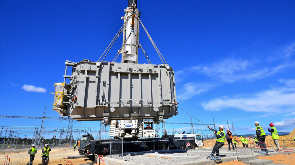
These units are large in size and heavy in weight. They are generally oil-immersed transformers installed outdoors in substations. Selecting such large equipment requires consideration of transportation routes, lifting conditions, and heat dissipation space. Electrical parameters alone are not sufficient.
These applications usually involve extremely large loads and high load rates. During design, more attention needs to be given to:
- Winding short-circuit mechanical strength (due to frequent heavy-load starting and higher short-circuit risks)
- Core flux density control (to prevent core saturation caused by over-excitation)
- Cooling method selection (large-capacity transformers generally use forced oil circulation and air cooling)
| Capacity Range | Typical Applications | Voltage Level | Installation Method |
|---|---|---|---|
| 50-200kVA | Small shops, rural electrification, residential areas | 10kV/0.4kV | Pole-mounted, compact substation |
| 250-1000kVA | Industrial plants, commercial complexes, medium-sized factories | 10kV/0.4kV | Compact substation, indoor installation |
| 1250-2500kVA | Large industries, data centers, industrial parks | 10-35kV/0.4kV | Outdoor, indoor installation |
| 3150-5000kVA | Mines, oil fields, regional substations | 35kV and above | Outdoor substation |
3.5 Quick Selection Reference Table
The following table provides a quick reference for scenarios where motor loads are the primary load type:
| Total Load Power Range | Recommended Transformer Capacity | Recommended Voltage Level |
|---|---|---|
| Below 20kW | 25-30kVA | 10kV/0.4kV |
| 20-40kW | 50kVA | 10kV/0.4kV |
| 40-80kW | 100kVA | 10kV/0.4kV |
| 80-160kW | 200kVA | 10kV/0.4kV |
| 160-250kW | 315kVA | 10kV/0.4kV |
| 250-400kW | 500kVA | 10kV/0.4kV |
| 400-600kW | 800kVA | 10kV/0.4kV |
| 600-800kW | 1000kVA | 10kV/0.4kV |
| 800-1200kW | 1600kVA | 10-35kV/0.4kV |
| 1200-1600kW | 2000kVA | 35kV/0.4kV |
| 1600-2000kW | 2500kVA | 35kV/0.4kV |
IV. Transformer Capacity Selection Steps
Step 1: Calculate the Load.
List the power ratings of all electrical equipment and classify them into normal operating loads, standby loads, and temporary loads.
This step often overlooks the special characteristics of standby equipment and fire protection equipment. These devices normally remain unused, but once activated, they may operate simultaneously. For example, fire pumps and sprinkler pumps do not usually operate under normal conditions, but during a fire emergency they may start together, creating a significant instantaneous load. However, they should not simply be included in the daily operating load calculation.
Step 2: Calculate the Actual Load.
Use the demand factor method or maximum load method to calculate the actual maximum operating load.
The demand factor method is suitable for projects with various types of equipment and different specifications. The maximum load method is suitable for applications with relatively stable loads. Both methods have their advantages, and in actual projects they are often calculated separately for cross-validation. If the difference between the two results exceeds 15%, it indicates that some assumptions may be unreasonable and the original data should be reviewed.
Step 3: Determine the Capacity.
Use the formula Se = S ÷ βm, where S represents the actual load and βm represents the load rate (generally around 0.8).
If the calculated result falls between standard capacity ratings, select the next higher standard capacity. For example, if the calculation result is 420kVA, directly select a 500kVA transformer.
Step 4: Select the Next Standard Capacity Level Upward.
Calculated values are often not standard ratings, so the closest higher standard capacity should be selected.
Step 5: Consider Special Factors.
Factors such as motor starting current impact, ambient temperature, harmonic content, and future expansion requirements should all be considered.
Ambient temperature is particularly easy to overlook. Domestic projects in cooler regions may pay less attention to this factor, but it must be carefully considered for export projects to the Middle East and Africa. Capacity adjustments should be made through derating during the design stage to prevent frequent summer tripping after commissioning.
V. Common Selection Mistakes
Mistake 1: Larger capacity means safer.
An oversized transformer increases initial investment and also increases no-load losses, making long-term operation uneconomical.
In some industrial park projects, capacity was designed too conservatively during the early stage, resulting in actual operating loads remaining below 40% for long periods. This increased both equipment investment and no-load losses. In one case, two 2500kVA transformers were selected during the design stage, but the actual load remained below 40% for years. The annual electricity cost caused by no-load losses and load losses exceeded the financing cost of purchasing the transformers. Eventually, the equipment had to be replaced with two 1600kVA units, causing significant losses from discounted disposal of the original transformers.
Mistake 2: Adding all equipment power ratings equals the required transformer capacity.
Equipment does not operate at full load simultaneously, so this calculation usually results in an oversized transformer.
Mistake 3: Ignoring load characteristics.
The starting impact of inductive loads such as motors and variable frequency drives places much higher requirements on equipment capacity compared with resistive loads.
Some customers only calculate lighting and air conditioning loads during selection but fail to consider elevators and fire pump starting currents. Excessive voltage drop during elevator startup can cause lighting supplied by the same transformer to flicker or trip, affecting user experience. When fire pumps start, they may even cause transformer overcurrent trips, creating risks during emergency situations.
Mistake 4: Ignoring ambient temperature.
Failing to apply derating in high-temperature regions may result in frequent transformer trips during summer operation.
Mistake 5: Not reserving expansion capacity.
Business expansion, increased production lines, and capacity growth are common. Without considering future requirements, the transformer may need to be replaced after only a few years.
The cost of expansion is not limited to replacing the transformer itself. Production downtime can also create significant losses. For example, if a production line stops for three days, the loss may exceed the cost of a transformer. It is recommended to reserve at least 15% additional capacity while meeting current requirements.
VI. Zisheng Electric’s Transformer Selection Support
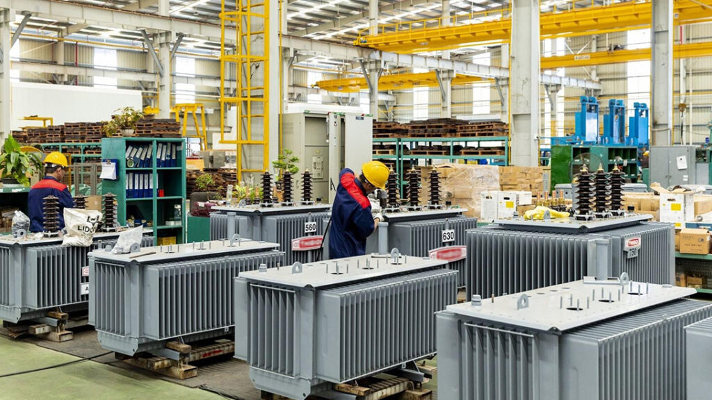
Zisheng Electric manufactures transformers and power equipment, with products covering oil-immersed transformers, dry-type transformers, amorphous alloy transformers, and switchgear. Products are customized and manufactured according to standards such as IEC 60076 and GOST, serving markets in the Middle East, South America, Africa, and Russia.
For transformer capacity selection, Zisheng Electric provides:
Load calculation and capacity confirmation.
Based on project equipment lists, operating conditions, and future development plans, Zisheng Electric assists with load calculations and capacity verification to avoid selecting transformers that are either oversized or undersized.
Voltage level matching.
According to the local grid conditions of the project location, Zisheng Electric confirms the high-voltage and low-voltage side voltage levels to ensure proper compatibility between the transformer and the power system.
Environmental adaptability design.
For operating conditions such as high temperature, high humidity, salt spray, and high altitude, capacity derating factors and protection measures are considered during the selection stage.
Special load adaptation.
For special loads such as groups of motors and variable frequency drive systems, sufficient capacity margins are reserved to ensure reliable startup and stable operation.
Technical documentation and project coordination.
Zisheng Electric provides technical data sheets, dimensional drawings, installation foundation drawings, and factory test reports, supporting EPC contractors and power companies throughout project delivery.
After-sales support.
After commissioning, Zisheng Electric provides operation monitoring, fault diagnosis, and maintenance guidance, creating a complete service cycle from selection to operation and maintenance.
VII. Conclusion
Selecting the proper transformer capacity essentially means accurately calculating the load, reserving sufficient margin, and matching standard capacity ratings. The principle is straightforward, but every step must be carefully implemented. Incorrect load statistics, misjudgment of load characteristics, or neglect of environmental conditions can all result in improper capacity selection.
A well-prepared capacity selection process during the design stage can prevent many problems later. Discovering insufficient transformer capacity after commissioning requires replacement costs and production downtime losses that are far greater than spending a few additional days on calculations during the early stage. Some people may think that spending extra time on preliminary analysis is unnecessary, but a project from design to commissioning often takes a year or even longer. Investing an additional week in accurate load analysis can provide stable operation and reasonable electricity costs for the next 20 years, making the effort worthwhile.
Zisheng Electric provides customized transformer capacity selection solutions and technical support based on specific project load conditions and operating environments.
Zisheng Electric — years of experience in power equipment R&D and manufacturing. Products include dry-type transformers, oil-immersed transformers, amorphous alloy transformers, and switchgear, with customized production available according to international standards such as IEC 60076 and GOST, serving markets in the Middle East, South America, Africa, and Russia. For confirmation of transformer capacity, technical parameters, voltage levels, installation methods, and quotation solutions, customers can provide project load lists, single-line diagrams, or technical specifications. Zisheng Electric’s engineering team will provide suitable solutions based on actual operating conditions.
About ZISHENG ELECTRICAL
Zisheng are a professional 19+ years manufacturer in producing Oil-Immersed Transformers, Compact Substation, Pad Mounted Transformers, Pole Mounted Transformers and Dry Type Transformers. We own the certificates of ISO/CE/IEC 60076 and TUV Rheinland.
Transformers undergo rigorous FAT and type testing, support voltage/capacity customization. Welcome to consult for Catalog and Product. you can contact us at email [email protected].