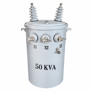
10 Key Technical Parameters and Selection Methods for Dry-Type Transformers
In industrial power distribution, building power supply, and new energy projects, dry-type transformers are widely used in indoor substations, data centers, rail transit systems, hospitals, and large industrial facilities due to their high fire-safety ratings, low maintenance requirements, and safe, reliable operation.
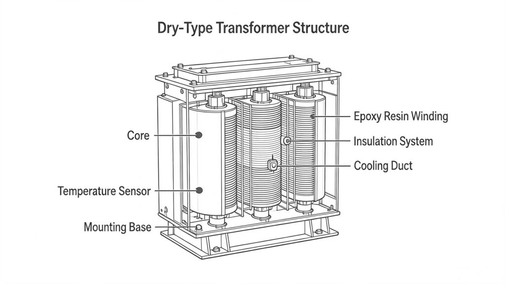
Compared to oil-immersed transformers, dry-type transformers utilize a solid insulation structure and do not require insulating oil for cooling or insulation; consequently, they pose no risk of oil leakage, offering distinct advantages for use in densely populated areas and locations with stringent fire safety requirements.
However, in practical engineering applications, the selection of a dry-type transformer is not determined solely by capacity. Parameters such as rated voltage, connection group, impedance voltage, loss levels, temperature rise, cooling method, and insulation class all influence the equipment’s operational performance and service life.
For instance, even among 2000 kVA dry-type transformers, differences in core materials, winding structures, and insulation systems employed by various manufacturers result in variations regarding no-load loss, load loss, temperature rise, and short-circuit withstand capability.
Therefore, during the equipment procurement and engineering design phases, it is essential to comprehensively evaluate key technical parameters based on the actual operating environment and load characteristics.
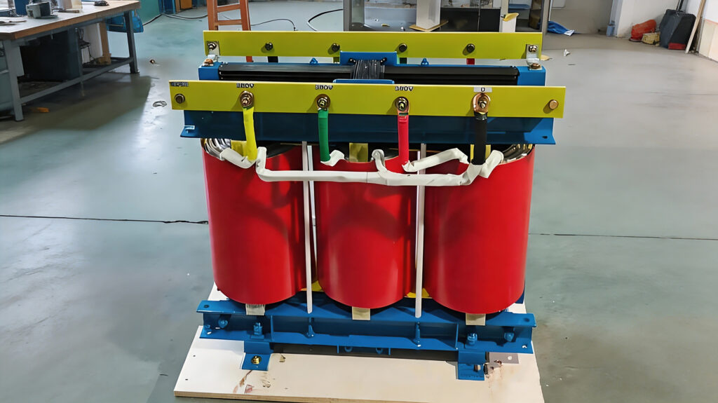
I. Number of Phases and Rated Frequency
1.Selection of Number of Phases
Dry-type transformers are primarily classified into two types based on the number of phases: single-phase and three-phase.
| Type | Characteristics | Main Applications |
|---|---|---|
| Single-phase Transformer | Small capacity, simple structure | Lighting systems and small equipment power supply |
| Three-phase Transformer | Large transmission capacity, high operating efficiency | Industrial power distribution and building power supply |
At present, three-phase dry-type transformers are the most widely used solution in industrial projects and building distribution systems.
For example, when a 10kV distribution system is stepped down to 0.4kV, the commonly used transformers include:
| Model | Capacity | Voltage Rating |
|---|---|---|
| SCB13-1000/10 | 1000kVA | 10/0.4kV |
| SCB13-1600/10 | 1600kVA | 10/0.4kV |
| SCB13-2000/10 | 2000kVA | 10/0.4kV |
| SCB13-2500/10 | 2500kVA | 10/0.4kV |
2.Rated frequency
Rated Frequency
The rated frequency refers to the power system frequency corresponding to the designed operating conditions of the transformer.
Power system frequencies vary among different countries and regions:
| Country/Region | Grid Frequency |
|---|---|
| China | 50Hz |
| Saudi Arabia | 60Hz |
| United Arab Emirates | 50Hz |
| Most European countries | 50Hz |
| United States | 60Hz |
Note: Some Middle Eastern countries operate on 60Hz power systems. Therefore, transformers for export projects must be designed according to the local grid standards.
If the transformer frequency does not match the power system frequency, it will affect the magnetic flux density, losses, and temperature rise.
The main impacts are as follows:
| Item | Impact |
|---|---|
| Core magnetic flux | May increase when frequency decreases |
| No-load current | May increase |
| Core temperature rise | Increases |
| Operating efficiency | Decreases |
Therefore, when purchasing dry-type transformers for overseas projects, the following parameters must be confirmed:
- System frequency
- Voltage level
- Ambient temperature
- Installation altitude
- Protection degree (IP rating)
II. Rated Voltage and Voltage Ratio
1.Rated Voltage
The rated voltage refers to the designed operating voltage of the transformer’s primary and secondary windings.
Common voltage combinations for dry-type transformers:
| High Voltage Side | Low Voltage Side | Application |
|---|---|---|
| 10kV | 0.4kV | Industrial plants, commercial buildings |
| 20kV | 0.4kV | Urban distribution systems |
| 35kV | 0.4kV | Large industrial projects |
Example: SCB13-2000/10 Dry-Type Transformer
| Parameter | Value |
|---|---|
| Model | SCB13-2000/10 |
| Rated Capacity | 2000kVA |
| High Voltage Side | 10kV |
| Low Voltage Side | 0.4kV |
| Frequency | 50Hz |
| Vector Group | Dyn11 |
| Cooling Method | AN/AF |
This transformer is designed for 10kV industrial distribution systems. After voltage reduction, it supplies power to low-voltage electrical equipment.
2.Voltage Ratio
The transformer voltage ratio represents the relationship between the primary-side voltage and the secondary-side voltage.
Calculation formula:
U₁/U₂ = N₁/N₂
Where:
- U₁: Primary-side voltage
- U₂: Secondary-side voltage
- N₁: Number of turns in the primary winding
- N₂: Number of turns in the secondary winding
Common Step-Down Applications:
| Input Voltage | Output Voltage | Application |
|---|---|---|
| 35kV | 0.4kV | Large industrial plants |
| 10kV | 0.4kV | General industrial power distribution |
| 6kV | 0.4kV | Certain mining and industrial systems |
The transformer voltage level must be properly matched with the power system.
If the equipment operates continuously at a voltage higher than its designed value, it may cause:
- Increased core magnetic flux density
- Higher no-load losses
- Increased temperature rise
- Accelerated insulation aging
Proper voltage matching is therefore essential to ensure transformer efficiency, reliability, and service life.
III. Rated Capacity
Rated capacity is one of the most important selection parameters for dry-type transformers, with the unit expressed in kVA.
It represents the maximum apparent power that a transformer can continuously deliver under specified operating conditions.
Calculation formula:
S = √3 × U × I
Where:
- S: Rated capacity
- U: Rated voltage
- I: Rated current
Common Capacity Ratings
| Capacity Range | Application |
|---|---|
| Below 100kVA | Small equipment power supply |
| 100–1600kVA | Commercial buildings and general industrial applications |
| 1600–3150kVA | Large industrial plants and data centers |
| Above 3150kVA | Large industrial projects and renewable energy projects |
Capacity Selection Principles
In actual engineering projects, transformer capacity should not be selected only based on the current load. The following factors should also be considered:
- Maximum present load
- Future load growth
- Motor starting current
- Overall operating economy
Generally, it is recommended that the transformer’s long-term operating load rate be maintained at approximately 70%–85%.
Low load operation:
- Higher initial investment
- Higher proportion of no-load losses
High load operation:
- Increased temperature rise
- Accelerated insulation aging
- Reduced service life
Engineering Application Case
A manufacturing project adopted a 10kV dry-type transformer power supply system.
Equipment Configuration
| Equipment | Quantity | Parameters |
|---|---|---|
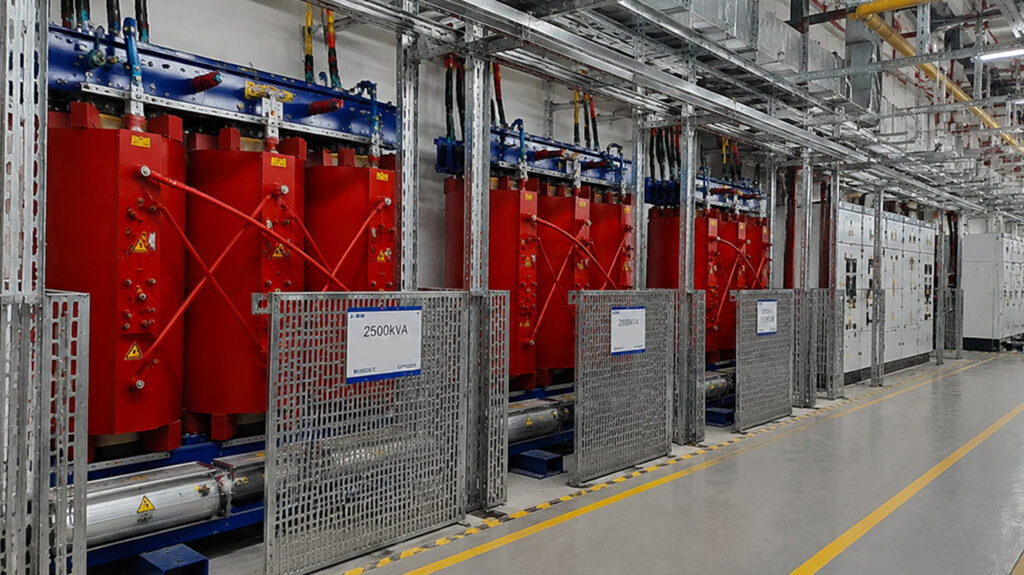
| Epoxy resin cast dry-type transformer | 4 units | 2500kVA, 10/0.4kV |
| Epoxy resin cast dry-type transformer | 6 units | 2000kVA, 10/0.4kV |
| Epoxy resin cast dry-type transformer | 2 units | 1000kVA, 10/0.4kV |
Main Applications
- Power supply for production equipment
- Process system power supply
- HVAC and ventilation systems
- Auxiliary power facilities
The equipment adopts Class H insulation materials and is designed according to Class F temperature rise limits, improving long-term operational reliability and extending service life.
IV. Winding Connection Group Designation
The vector group designation is used to indicate the connection method of the high-voltage and low-voltage windings of a dry-type transformer, as well as the phase displacement relationship between the two sides.
In engineering applications, the vector group not only affects the operating mode of the power supply system, but also directly influences parallel operation of transformers, harmonic control, and coordination with protection devices.
1. Composition of Vector Group Designation
The transformer vector group is generally represented by a combination of letters and numbers.
Example: Dyn11
| Symbol | Meaning |
|---|---|
| D | High-voltage winding connected in delta (Δ) |
| y | Low-voltage winding connected in star (Y) |
| n | Neutral point of the low-voltage side is brought out |
| 11 | Phase displacement of 30° between high-voltage and low-voltage sides |
2. Common Connection Types
| Vector Group | Connection Method | Application |
|---|---|---|
| Yyn0 | High-voltage star connection, low-voltage star connection | Small-capacity distribution systems |
| Dyn11 | High-voltage delta connection, low-voltage star connection with neutral point | Most widely used in industrial and commercial power distribution |
| Yd11 | High-voltage star connection, low-voltage delta connection | High-voltage substations |
| Dd0 | Both high-voltage and low-voltage windings connected in delta | Special industrial applications |
3. Why Is Dyn11 Widely Used?
In current 10kV/0.4kV distribution systems, Dyn11 is the most commonly used transformer vector group.
The main reasons include:
(1) Improved Third Harmonic Suppression
The high-voltage side adopts a delta connection, which provides a closed path for third harmonic currents, reducing voltage waveform distortion and improving power quality.
(2) Better Adaptability to Unbalanced Loads
Industrial plants and commercial buildings contain a large number of single-phase loads, such as:
- Lighting systems
- Office equipment
- Control systems
The Dyn11 configuration provides better tolerance to three-phase load imbalance and improves system stability.
(3) Improved Low-Voltage Side Grounding Protection
The neutral point of the low-voltage side is brought out, allowing the formation of a reliable grounding system and improving the operating reliability of protection devices.
V. Impedance Voltage and Load Loss
1. Impedance Voltage
Impedance voltage (Uk%) is one of the most important performance parameters of a transformer.
It represents the percentage of rated primary voltage that must be applied to the transformer primary side when the secondary side is short-circuited, in order to produce the rated current.
Calculation formula:Uk%=U1Uz×100%
Where:
- Uz: Short-circuit test voltage
- U1: Rated primary voltage
2. Impact of Impedance Voltage on Operation
The impedance voltage directly affects:
- Short-circuit current
- Voltage regulation
- System stability
| Impedance Voltage | Advantages | Disadvantages |
|---|---|---|
| Lower impedance voltage | Smaller voltage drop, higher efficiency | Higher short-circuit current |
| Higher impedance voltage | Better limitation of short-circuit current | Larger voltage drop |
Typical Impedance Voltage of Dry-Type Transformers
| Capacity | Typical Impedance Voltage |
|---|---|
| Below 630kVA | 4%-6% |
| 800-2500kVA | 6%-8% |
| Above 3150kVA | 8%-10% |
Example: SCB13-2000/10 Dry-Type Transformer
| Parameter | Value |
|---|---|
| Rated Capacity | 2000kVA |
| Impedance Voltage | 6% |
| Vector Group | Dyn11 |
| Voltage Rating | 10/0.4kV |
3. Load Loss
Load loss is mainly caused by the resistance of the transformer windings, and is also known as copper loss.
Calculation formula:Pcu=I2R
When the transformer load increases, the winding current increases, causing copper loss to rise rapidly.
For example, for the same 2000kVA dry-type transformer:
- At 50% load operation:
- Lower copper loss
- Lower temperature rise
- At 100% load operation:
- Significantly increased copper loss
- Higher winding temperature
Therefore, during long-term operation, the transformer load rate should be properly controlled to maintain efficiency and extend service life.
3. Load Loss
Load loss is mainly caused by the resistance of the transformer windings, and is also known as copper loss.
Calculation formula:Pcu=I2R
Where:
- Pcu: Load loss (copper loss)
- I: Winding current
- R: Winding resistance
As the transformer load increases, the winding current increases, causing copper loss to rise rapidly.
For example, for the same 2000kVA dry-type transformer:
- Operating at 50% load:
Copper loss is relatively low; temperature rise is limited. - Operating at 100% load:
Copper loss increases significantly; winding temperature rises accordingly.
Therefore, during long-term operation, the transformer load rate should be properly controlled to ensure reliable performance, reduce energy losses, and extend the service life of the insulation system.
VI. Temperature Rise and Cooling Methods
1. Importance of Temperature Rise
Unlike oil-immersed transformers, dry-type transformers do not have an oil circulation cooling system. Therefore, winding temperature control mainly relies on:
- Ambient air circulation
- Winding structure design
- Forced cooling by fans
The main heat sources generated during transformer operation include:
| Heat Source | Cause |
|---|---|
| Core loss | Hysteresis loss and eddy current loss |
| Winding loss | Heat generated by winding resistance |
| Structural component loss | Additional losses caused by leakage flux |
2. Insulation Class
Common insulation classes used in dry-type transformers:
| Insulation Class | Maximum Allowable Temperature | Application |
|---|---|---|
| Class B | 130℃ | General-purpose equipment |
| Class F | 155℃ | Mainstream dry-type transformers |
| Class H | 180℃ | High-temperature environments |
Currently, epoxy resin cast dry-type transformers used in industrial projects typically adopt:
Class H insulation materials + Class F temperature rise design
This design approach helps reduce actual operating temperature, improve thermal performance, and extend the service life of the transformer.
3. Cooling Methods
The cooling methods of dry-type transformers are mainly divided into:
| Cooling Method | Description | Application |
|---|---|---|
| AN | Natural air cooling | Small-capacity dry-type transformers |
| AF | Forced air cooling | Large-capacity dry-type transformers |
Example: SCB13-2000/10 dry-type transformer
- Normal operation: AN natural air cooling
- High-load operation: AF fan cooling activated to improve heat dissipation capability
VII. Insulation System of Dry-Type Transformers
The operational stability and reliability of dry-type transformers largely depend on the insulation material system.
The most widely used insulation method is:
Epoxy Resin Cast Insulation
Its main characteristics include:
- Excellent moisture resistance
- High mechanical strength
- Low partial discharge level
- Good adaptability to industrial environments
Main Insulation Materials
| Material | Function |
|---|---|
| Epoxy resin | High-voltage winding insulation encapsulation |
| Glass fiber | Improves mechanical strength |
| DMD insulation material | Layer insulation between windings |
| Polyester film | Turn-to-turn insulation |
| Mica material | Improves heat resistance performance |
Application Requirements for High-Temperature Environments in the Middle East
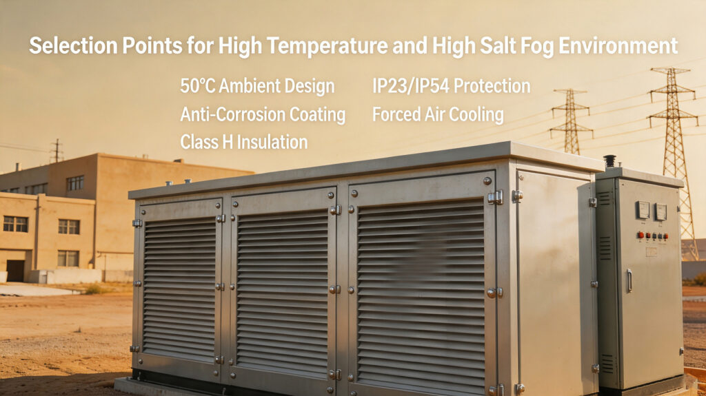
Application Requirements for Dry-Type Transformers in High-Temperature Environments
In regions such as Saudi Arabia and the United Arab Emirates, dry-type transformers typically need to meet the following requirements:
| Item | Requirement |
|---|---|
| Ambient Temperature | 50℃ |
| Protection Rating | IP23/IP54 |
| Insulation Class | Class F / Class H |
| Corrosion Protection | Enhanced anti-corrosion treatment |
| Design Standard | IEC 60076 |
In high-temperature environments, insufficient heat dissipation capability may lead to:
- Increased winding temperature rise
- Accelerated insulation aging
- Reduced service life
Therefore, dry-type transformers used in Middle Eastern industrial projects are usually designed with increased temperature-rise margins.
VIII. Typical Engineering Application Case of Dry-Type Transformers
1. Jubail Industrial City Power Workshop Project, Saudi Arabia
Jubail Industrial City, located in Saudi Arabia’s Eastern Province, is one of the most important petrochemical and industrial manufacturing bases in the Middle East.
The region is continuously exposed to harsh environmental conditions, including:
- High temperature
- High humidity
- Salt mist corrosion
- Dust and sand
These conditions place high requirements on the environmental adaptability and reliability of electrical equipment.
The project power workshop adopted dry-type transformers as the main power distribution equipment, providing stable power supply for:
- Production equipment
- Auxiliary power systems
- Plant low-voltage distribution systems
Project Configuration
| Equipment Type | Quantity | Main Parameters |
|---|---|---|
| Epoxy resin cast dry-type transformer | 12 units | 10kV/0.4kV |
| Packaged substation | 10 units | 10kV/0.4kV |
| Dry-type transformer capacity | — | 2500kVA, 2000kVA, 1000kVA |
Main Equipment Parameters
2500kVA Dry-Type Transformer
| Parameter | Technical Specification |
|---|---|
| Model | SCB13-2500/10 |
| Rated Capacity | 2500kVA |
| High Voltage Side | 10kV |
| Low Voltage Side | 0.4kV |
| Frequency | 50Hz |
| Vector Group | Dyn11 |
| Insulation Method | Epoxy resin cast insulation |
| Insulation Class | Class H |
| Cooling Method | AN/AF |
| Protection Rating | IP23/IP54 |
2000kVA Dry-Type Transformer
| Parameter | Technical Specification |
|---|---|
| Model | SCB13-2000/10 |
| Rated Capacity | 2000kVA |
| High Voltage Side | 10kV |
| Low Voltage Side | 0.4kV |
| Rated Frequency | 50Hz |
| Vector Group | Dyn11 |
| Impedance Voltage | 6% |
| Cooling Method | AN/AF |
| Insulation Material | Epoxy Resin |
1000kVA Dry-Type Transformer
| Parameter | Technical Specification |
|---|---|
| Model | SCB13-1000/10 |
| Rated Capacity | 1000kVA |
| High Voltage Side | 10kV |
| Low Voltage Side | 0.4kV |
| Frequency | 50Hz |
| Vector Group | Dyn11 |
| Cooling Method | AN |
| Insulation Class | Class F / Class H |
Project Design Features
Considering the operating environment in Jubail, the key design considerations include:
1. High-Temperature Adaptability
The equipment is designed for a 50℃ ambient temperature, improving winding heat dissipation capability.
Main measures include:
- Increasing thermal design margin
- Optimizing winding structure
- Installing forced air cooling systems
2. Salt Mist Corrosion Protection
Coastal areas contain high concentrations of chloride ions in the air, which can accelerate corrosion of metal components.
The equipment adopts:
- Anti-corrosion coatings
- Stainless steel fasteners
- Enhanced surface treatment
3. Dust Protection Design
Industrial areas often contain large amounts of dust, which may affect insulation performance if it enters the equipment.
Protection measures include:
- IP23/IP54 protection rating
- Sealed enclosure structure
- Optimized ventilation and filtration design
IX. Summary of Key Selection Parameters for Dry-Type Transformers
In practical projects, the main parameters considered for dry-type transformer selection include:
| Parameter | Description | Selection Requirement |
|---|---|---|
| Rated Capacity | Output capability | Selected according to maximum load demand |
| Rated Voltage | Voltage level | Must match the power system |
| Frequency | System frequency | 50Hz or 60Hz |
| Vector Group | Winding connection method | Dyn11 commonly used |
| Impedance Voltage | Short-circuit impedance | Determined according to system requirements |
| No-load Loss | Core loss | Affects long-term operating cost |
| Load Loss | Winding loss | Affects full-load efficiency |
| Temperature Rise | Heat generation level | Affects insulation life |
| Insulation Class | Thermal endurance capability | Class F/H commonly used |
| Cooling Method | Heat dissipation method | AN/AF |
X. Operation and Maintenance Requirements for Dry-Type Transformers
Although dry-type transformers require less maintenance compared with oil-immersed transformers, regular inspections are still necessary during long-term operation.
Main Inspection Items
| Inspection Item | Purpose |
|---|---|
| Temperature Monitoring | Determine whether winding temperature rise is normal |
| Load Monitoring | Check whether the equipment is overloaded |
| Insulation Testing | Evaluate insulation aging condition |
| Sound Inspection | Detect abnormal conditions in the core and structure |
| Visual Inspection | Check dust accumulation, cracks, and corrosion |
Common Operating Problems
1. Excessive Temperature Rise
Possible causes:
- Long-term overload operation
- Insufficient ventilation
- Cooling fan failure
- Excessively high ambient temperature
Corrective measures:
- Reduce load
- Check the cooling system
- Clean ventilation channels
2. Increased Partial Discharge
Possible causes:
- Winding contamination
- Moisture absorption in insulation
- Cracks in epoxy resin insulation
Corrective measures:
- Perform regular partial discharge testing
- Inspect insulation condition
- Keep the transformer clean and dry
About ZISHENG ELECTRICAL
Zisheng are a professional 19+ years manufacturer in producing Oil-Immersed Transformers, Compact Substation, Pad Mounted Transformers, Pole Mounted Transformers and Dry Type Transformers. We own the certificates of ISO/CE/IEC 60076 and TUV Rheinland.
Transformers undergo rigorous FAT and type testing, support voltage/capacity customization. Welcome to consult for Catalog and Product. you can contact us at email [email protected].